HAND-HELD DISPLAY MODULE
3-8
ChromaFlex Chassis – Operation Manual
ATX Confi dential & Proprietary
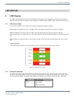
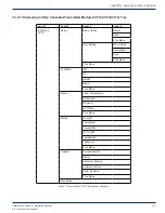
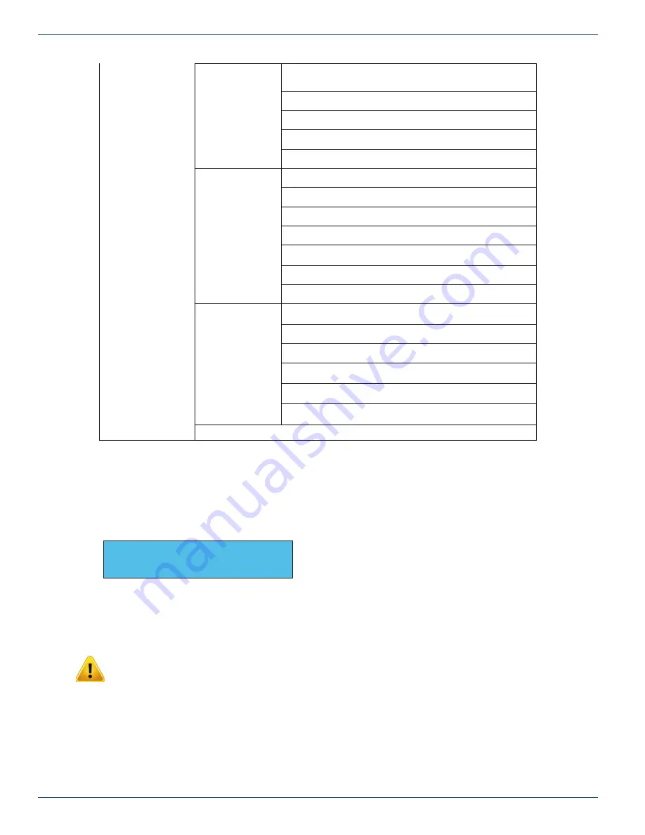
Alarm
Laser Temperature
OPT Out Pwr
RF Level
Module Tmp
Prev Menu
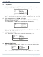
Status
Laser Temp(C)
OPT Out (dBm)
Att(dB)
RF Lvl(dB)
Lambda(nm)
Voltage(V)
Prev Menu
Chassis
Temperature(C)
Model
Hardware Version
Software Version
Serial Number
Prev Menu
Prev Menu
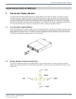
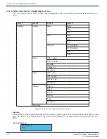
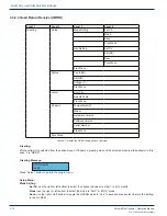
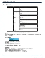
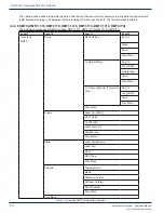
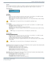
Table 3: ChromaFlex CCT1 Display Menu Overview
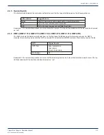
Greeting:
After a valid slot is selected from the option menu of Chassis, a greeting menu of the selected module will be shown; in this
case, it is “CCT1”. For CCT1 with variable output, this would read “CCT1-VO”.
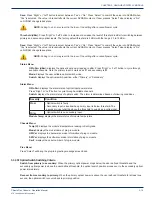
Greeting Message:
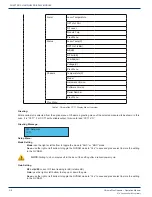
Setup Menu:
Mode Setting
Mode:
use the right or left bottom to toggle the mode to “AGC” or “MGC” mode.
Save:
use the right or left bottom to toggle the NVRAM mode to “Yes” to save and press select to store the setting
in the NV RAM.
NOTE: Failing to do so may result in the loss of the setting after a reboot/power cycle.
Gain Setting
RF Lvl(rdB):
current RF level reading in rdB (relative dB).
Gain:
use the right or left bottom to step up or down the gain.
Save:
use the right or left bottom to toggle the NVRAM mode to “Yes” to save and press select to store the setting
in the NV RAM.
ATX Networks
CCT1
CHAPTER 3: