LED DISPLAY
ChromaFlex Chassis – Operation Manual
2-3
ATX Confidential & Proprietary
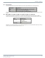
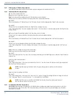
2.3.5 Optical Switch
The Optical Switch detects the alarms and reflects them on the front panel LEDs based on the following schema.
LED Location
Trigger Events
Status
Alarm(s) triggered by switch alarm and/or module temp alarm
PRI
Opt In Pwr level crosses alarm thresholds
SEC
Opt In Pwr level crosses user settable thresholds
Example #1: The module temperature is normal, but switch is major. The top LED associated with the slot shall be observed
as “red”.
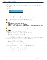
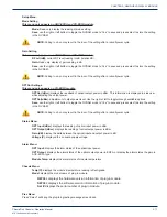
2.3.6 DMTx (DMT2 1310, DMT2 ITU, DMT3 1310, DMT3 ITU, DMT4 1310, DMT4 ITU)
The DMTx detects the alarms and reflects them on the front panel LEDs based on the following schema. For DMT3
modules, there are three pairs of LEDs (OPT on top and RF on bottom) and DMT4 modules, there are four pairs of LEDs.
LED
Trigger Events
OPT (Top)
Laser temperature
Laser power
Module temperature
RF (Bottom)
RF
Example #1: The module temperature is normal, but the laser temperature is at a level that indicates a major alarm. The top
LED associated with the interface shall be observed as “red”.
CHAPTER 2:


