background image

CHAPTER 1:  

DigiVu

®

 Series Multichannel MPEG-2/H.264 Encoder/Multiplexer with QAM &/or IP Output - Installation & Operation Manual 

v

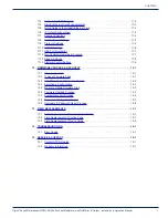
11.3  Support for VLAN Tagging . . . . . . . . . . . . . . . . . . . . . . . . . . . . . . . . . . . . . . . . . .11-3
11.4  Gigabit Ethernet Card Fundamentals . . . . . . . . . . . . . . . . . . . . . . . . . . . . . . . . . .11-3
11.5  Quick Guide to the Gigabit Ethernet Card  . . . . . . . . . . . . . . . . . . . . . . . . . . . . . .11-3
11.6  IP Output Configuration  . . . . . . . . . . . . . . . . . . . . . . . . . . . . . . . . . . . . . . . . . . . .11-4
11.7  Source IP Settings . . . . . . . . . . . . . . . . . . . . . . . . . . . . . . . . . . . . . . . . . . . . . . . .11-4
11.8  Destination IP Settings . . . . . . . . . . . . . . . . . . . . . . . . . . . . . . . . . . . . . . . . . . . . .11-5
11.9  Protocol Settings. . . . . . . . . . . . . . . . . . . . . . . . . . . . . . . . . . . . . . . . . . . . . . . . . .11-5
11.10  VLANS Settings . . . . . . . . . . . . . . . . . . . . . . . . . . . . . . . . . . . . . . . . . . . . . . . . . .11-6
11.11  GbE Port Numbering  . . . . . . . . . . . . . . . . . . . . . . . . . . . . . . . . . . . . . . . . . . . . . .11-7
11.12  Two VLANs Automatically Created . . . . . . . . . . . . . . . . . . . . . . . . . . . . . . . . . . . .11-7
11.13  Stream Settings  . . . . . . . . . . . . . . . . . . . . . . . . . . . . . . . . . . . . . . . . . . . . . . . . . .11-8
11.14  Platform Control Buttons. . . . . . . . . . . . . . . . . . . . . . . . . . . . . . . . . . . . . . . . . . . .11-9

12.  FIRMWARE UPGRADE & RECOVERY  . . . . . . . . . . . . . . . . . . . . . . . . . . . . . . . . . . . . 12-1

12.1  Chapter Contents . . . . . . . . . . . . . . . . . . . . . . . . . . . . . . . . . . . . . . . . . . . . . . . . 12-1
12.2  Types of Firmware Files . . . . . . . . . . . . . . . . . . . . . . . . . . . . . . . . . . . . . . . . . . . 12-1
12.3  Identifying Current Firmware Version . . . . . . . . . . . . . . . . . . . . . . . . . . . . . . . . . 12-2
12.4  Exporting a Configuration . . . . . . . . . . . . . . . . . . . . . . . . . . . . . . . . . . . . . . . . . . 12-2
12.5  Where to Obtain Firmware Files . . . . . . . . . . . . . . . . . . . . . . . . . . . . . . . . . . . . . 12-3
12.6  Firmware Upgrade Process . . . . . . . . . . . . . . . . . . . . . . . . . . . . . . . . . . . . . . . . 12-3
12.7  System Recovery Process . . . . . . . . . . . . . . . . . . . . . . . . . . . . . . . . . . . . . . . . . 12-5
12.8  Restore a Configuration Export  . . . . . . . . . . . . . . . . . . . . . . . . . . . . . . . . . . . . . 12-7
12.9  Username & Password Reset Process. . . . . . . . . . . . . . . . . . . . . . . . . . . . . . . .  12-8

13.  FIELD REPLACEMENTS  . . . . . . . . . . . . . . . . . . . . . . . . . . . . . . . . . . . . . . . . . . . . . . . 13-1

13.1  Field Replacement of Realtime Clock Battery  . . . . . . . . . . . . . . . . . . . . . . . . . . 13-1
13.2  Field Replacement of Cooling Fans . . . . . . . . . . . . . . . . . . . . . . . . . . . . . . . . . . 13-1
13.3  Field Replacement of Plug-in Cards  . . . . . . . . . . . . . . . . . . . . . . . . . . . . . . . . . 13-2

14.  TROUBLESHOOTING  . . . . . . . . . . . . . . . . . . . . . . . . . . . . . . . . . . . . . . . . . . . . . . . . . 14-1

14.1  Error Codes  . . . . . . . . . . . . . . . . . . . . . . . . . . . . . . . . . . . . . . . . . . . . . . . . . . . . 14-1

15.  SERVICE & SUPPORT . . . . . . . . . . . . . . . . . . . . . . . . . . . . . . . . . . . . . . . . . . . . . . . . . 15-1

15.1  Contact ATX Networks . . . . . . . . . . . . . . . . . . . . . . . . . . . . . . . . . . . . . . . . . . . . 15-1
15.2  Warranty Information  . . . . . . . . . . . . . . . . . . . . . . . . . . . . . . . . . . . . . . . . . . . . . 15-1

Summary of Contents for DigiVu

Page 1: ...Multichannel MPEG 2 H 264 Encoder Multiplexer QAM IP Output Installation Operation Manual ...

Page 2: ...der is viewing the Adobe PDF file directly Hyperlinks may be identified by their blue text Most links are to related pages within the document but some reference outside documents if the reader needs that additional information The Table of Contents is entirely hyperlinked and bookmarks are available but the bookmark feature must be turned on in your Reader application Symbol Usage Throughout the ...

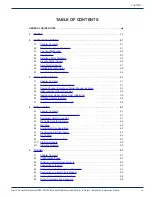
Page 3: ... 3 2 3 4 QAM Insertion Without Decoding 3 3 3 5 Insertion Into Under utilized QAM Add Drop 3 4 3 6 IP Video Content Insertion 3 5 3 7 Local Content Back Haul Over IP 3 6 4 INSTALLATION 4 1 4 1 Chapter Contents 4 1 4 2 Recommended Installation Environment 4 1 4 3 Equipment Safety Grounding 4 1 4 4 RF Cable Sheath Grounding 4 2 4 5 Mounting 4 2 4 6 Environment Considerations 4 3 4 7 Provisioning Ele...

Page 4: ... 7 2 7 4 DVB SI Settings 7 2 7 5 No Video Slide Enable 7 3 7 6 Platform Control Buttons 7 3 8 RF OUTPUT TAB 8 1 8 1 RF Settings 8 1 8 2 Platform Control Buttons 8 2 9 MAINTENANCE TAB 9 1 9 1 Chapter Contents 9 1 9 2 DVIS Information 9 2 9 3 DVIS Hardware Status 9 2 9 4 SNMP Settings 9 2 9 5 Remote Update Server 9 3 9 6 Platform Control Buttons 9 3 9 7 Network Settings 9 6 9 8 Platform Network Cont...

Page 5: ...11 14 Platform Control Buttons 11 9 12 FIRMWARE UPGRADE RECOVERY 12 1 12 1 Chapter Contents 12 1 12 2 Types of Firmware Files 12 1 12 3 Identifying Current Firmware Version 12 2 12 4 Exporting a Configuration 12 2 12 5 Where to Obtain Firmware Files 12 3 12 6 Firmware Upgrade Process 12 3 12 7 System Recovery Process 12 5 12 8 Restore a Configuration Export 12 7 12 9 Username Password Reset Proces...

Page 6: ...CHAPTER 1 vi DigiVu Series Multichannel MPEG 2 H 264 Encoder Multiplexer with QAM or IP Output Installation Operation Manual ...

Page 7: ...he duplex wall receptacle be current limited to 15 A maximum NOTE a Replace fuse in units operating on 115 VAC supply by fuse rated 3 0 A 250 V slo blo b Replace fuse in units operating on 230 VAC supply by fuse rated 1 5 A 250 V slo blo CAUTION For continued protection against the risk of fire replace only with the same type and rating of fuse POWER SUPPLY REMOVAL Disconnect power AC or DC from t...

Page 8: ...tances create a fire hazard Connection to a cable distribution system has therefore to be provided through a device providing electrical isolation below a certain frequency range galvanic isolator per EN 60728 11 a galvanic isolator shall provide electrical insulation below 5 MHz The insulation shall withstand a dielectric strength of 1 5 kV r m s 50 Hz or 60 Hz for 1 min Utrustning som är kopplad...

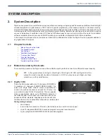
Page 9: ...e DigiVu Encoder Key Features Simplified Block Diagrams Front and Rear Panels Card Slot Numbering Available Encoder Cards Available Input Output Cards 2 2 Models Covered by this Guide There are three models in the DigiVu series all have QAM output by default but each has different channel capacity FYI In this guide reference to DigiVu infers DigiVu 3RU DigiVu CD 3RU and DigiVu Mini 1RU unless the ...

Page 10: ...r encoders or I O cards Up to 4 integrated SD MPEG 2 encoded programs using dual encoder cards Up to 2 integrated SD HD MPEG 2 H 264 programs encoded 2 3 The DigiVu Encoder DigiVu series products are headend or network edge local content encoding devices for digital video networks They encode local baseband analog content into a digital format at the headend or within a property provisioned with d...

Page 11: ...AM or IP multiplex or alternately may be used in an add drop application along with an optional plug in demodulator card to insert programs into an existing QAM clear or encrypted replacing only the programs that are desired If the program that is dropped was encrypted the replacement program stream will be in the clear The add drop application utilizes the QAM demodulator to analyze the MPEG stre...

Page 12: ...rriers The DigiVu CD may be configured with an optional channel deletion filter which allows the removal of any EIA channel and all of it s RF content with minimal adjacent channel affect allowing a new QAM channel to be inserted 2 4 11 Powerful GUI Management and configuration of the DigiVu system is through a built in web server which presents the configuration pages in an intuitive tabbed forma...

Page 13: ...L RF OUT RF OUT TEST 20 dB 20 dB QAM DEMODULATOR TO DEMODULATOR PATCH CABLE VIDEO IN PLUG IN CARDS FAN POWER SUPPLY RJ 45 INTERFACE LAPTOP PC 90 264 VAC L R AUDIO IN VIDEO IN L R AUDIO IN VIDEO IN L R AUDIO IN VIDEO IN L R AUDIO IN ON OFF SWITCH DEMODULATOR CARD ENCODER CARDS RF SWITCH RF SWITCH 20 dB FAN RF DETECTOR RF SWITCH 20 dB RESET REBOOT 1 OR 2 CHANNEL ENCODER 1 OR 2 CHANNEL ENCODER TS MUL...

Page 14: ...Output Test Point Figure 2 7 DigiVu Front Power Switch Management Ethernet Port RF Output Port Reboot Button Reset Button Power Indicator Encoder and I O Card Slots Figure 2 8 DigiVu Rear Realtime Clock Battery RF Output Test Point RF Input Test Point Channel Dropping Filter Figure 2 9 DigiVu CD Front Encoder and I O Card Slots Power Switch Management Ethernet Port RF Output Port Reboot Button Res...

Page 15: ... card guides when re inserting the cards NOTE The 6th card slot in the DigiVu 3RU platforms is for power only to cards which do not require management as this slot does not show up in the GUI Currently this slot is exclusively used for the 2 Way A V Splitter card but the A V Splitter card may be installed in any slot if required FYI For information on the way the GUI displays installed cards see 6...

Page 16: ... 2 Single Channel SD Encoder 1 2 3 4 5 1 2 Dual Channel SD Encoder 1 2 3 4 5 1 2 Demodulator 1 2 3 4 5 1 2 Gigabit Ethernet 5 2 2 Way Audio Video Splitter 1 2 3 4 5 AUX 1 2 NOTE All cards are hot pluggable so there is no need to interrupt power to change cards 2 8 Available Encoder Cards 2 8 1 DV1CE DV1CEM Single Channel SD Card 2 8 2 DV2CE DV2CEM Dual Channel SD Card 2 8 3 DV1HDA Single Channel H...

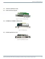
Page 17: ... IP Output Installation Operation Manual 2 9 2 9 Available Input Output Cards 2 9 1 DV1DA Distribution Amplifier 2 9 2 DVDMQMB DVDMQMAC QAM Modulator 2 9 3 DVGIGE Gigabit Ethernet Card Figure 2 18 2 Output A V Distribution Amplifier Figure 2 19 QAM Demodulator Figure 2 20 Gigabit Ethernet Output Card ...

Page 18: ...CHAPTER 2 SYSTEM DESCRIPTION DigiVu Series Multichannel MPEG 2 H 264 Encoder Multiplexer with QAM or IP Output Installation Operation Manual 2 10 This page intentionally left blank ...

Page 19: ...etween existing adjacent system channels and at the upper edge of the cable system passband See QAM Insertion Without Decoding on page 3 3 3 2 2 Insertion of a Carrier with use of a Deletion Filter to Remove an Existing Carrier Using the optional channel deletion filter the target system channel may be effectively removed to make space for the inserted channel In this case adjacent system channels...

Page 20: ...OUPLER NEW PROGRAM ANALOG CHANNEL MODULATOR AUDIO VIDEO NEW CHANNEL SOURCE MATERIAL New Way All Digital System One Channel can typically contain up to 10 programs One channel is deleted Any number of programs within that channel can be dropped One to Four new programs can be added modulated and inserted The new channel can only be tuned with a Digital Set Top Box DIGITAL CHANNEL DIGITAL CHANNEL DI...

Page 21: ... filter When RF spectrum is available for this application and or there are a large number of insertion systems installed the cost of a channel deletion filter may be saved at every property 3 4 2 Insertion Into Channel at Band Edge There are two main scenarios for this deployment Regular 870 MHz plant has some empty channels remaining unused just below 870 MHz The new QAM channel is inserted on o...

Page 22: ...filter is available from ATX Networks and is an integral part of the design of the DigiVu CD In this case the DigiVu CD will create a totally new QAM channel and insert it into the blank spectrum following the output of the filter 3 5 Insertion Into Under utilized QAM Add Drop 3 5 1 Locally Add Drop Programs in a QAM The DigiVu CD can be used to insert local programming into the actual data stream...

Page 23: ... be inserted Replaced programs will be in the clear This has the benefit of retaining programs in the QAM that must remain and using the deleted program space to provide the local content to the property Only content payload is manipulated dropped replaced added All other data tables from incoming QAM is passed through without affecting it 3 6 IP Video Content Insertion The DigiVu platform with Gb...

Page 24: ...n into the plant There are two main applications as illustrated in Figure 3 6 1 Fiber Back Haul This provides guaranteed signal quality link speed and bandwidth In this case a single mode SFP may be used to transport the IP stream on the fiber 2 DOCSIS modem Back Haul Not always possible to guarantee link speed and bandwidth which could vary therefore encoded signal quality must be lower due to lo...

Page 25: ...in a fixed position and should be installed securely before operation is undertaken 4 3 Equipment Safety Grounding It is imperative that the chassis be connected to a permanent building ground in a manner that will ensure that the exposed metal parts are constantly connected to ground even when the power cord may be disconnected temporarily A grounding lug is provided on the front panel to conveni...

Page 26: ...ing 4 5 1 Rack Mounting The chassis is intended to be mounted in a standard 19 EIA equipment rack A reasonable amount of space will be required in front of and behind to allow installation and servicing The equipment is designed with fan forced cooling which exhausts to the top and side of the unit Avoid blocking airflow at the top and sides and mount in such a manner to provide a source of ambien...

Page 27: ... such that the provided power supply cord may be routed in an appropriate manner without the use of extension cords between the receptacle and the chassis Alternately the chassis shall be installed in close proximity to an existing electrical outlet such that the requirements of this paragraph are achieved 4 7 4 IEC Power Input Cord The power input receptacle is a standard IEC connector similar to...

Page 28: ... the input specification is met External RF attenuators and couplers that may be necessary depend on site conditions and are not supplied 4 8 3 RF Output Level The RF output connector is 75 Ω F Type female The output level from the QAM modulator is 57 5 1 5 dBmV The GUI provides an internal adjustable attenuator of up to 26 dB in 1 dB steps to reduce this level to match application specific RF lev...

Page 29: ...edance unbalanced Be sure to match the audio source to the DigiVu audio connection Usually double or triple shielded 75 Ω coaxial cables may be used with satisfactory results If balanced audio is encountered it is often possible to obtain good results by using only the side of the feed 4 10 Ethernet Network 4 10 1 Ethernet Port A front panel Ethernet network port is provided on the DigiVu Mini 1RU...

Page 30: ...CHAPTER 4 INSTALLATION 4 6 DigiVu Series Multichannel MPEG 2 H 264 Encoder Multiplexer with QAM or IP Output Installation Operation Manual This page intentionally left blank ...

Page 31: ...s The GUI may be accessed remotely over the internet or any private intranet if such access is made available FYI In this guide reference to DigiVu infers DigiVu 3RU DigiVu CD 3RU and DigiVu Mini 1RU unless the model is specifically stated Reference to DVIS is synonymous with DigiVu as these products run on the same firmware 5 1 Chapter Contents Configuration Pages Minimum Computer Requirements Co...

Page 32: ...re updates as well as import of a previously exported configuration file Log Used for troubleshooting by ATX Networks support engineers Figure 5 2 Description of Configuration Tabs 5 3 Minimum Computer Requirements The computer used to access the DigiVu configuration settings is referred to as the Management Computer It is recommended that the Management Computer meet the minimum requirements list...

Page 33: ... them so the network adapter may be readily returned to these values again a From the Control Panel open Network Connections and select the connection associated with the wired Ethernet adapter to be used for connecting to the DigiVu e g Local Area Connection b Right click on the connection then select Properties c Select Internet Protocol TCP IP and click Properties d Click the selection box besi...

Page 34: ...uired to connect the Ethernet port directly to a PC The network port will automatically negotiate a speed of 10 or 100 Mbps depending on the capabilities of the PC network port A light next to the DigiVu Ethernet port will illuminate amber when a link is negotiated FYI If connectivity problems between the PC network port and the DigiVu occur Ethernet link light does not illuminate check to be sure...

Page 35: ...ference 3 Select the check box marked DHCP Client Mode Enabled and then click Set Network 4 In the confirmation window that appears click Yes to confirm the change to the network parameters 5 The unit will reboot and fans will shut down then restart 6 An error messages will be displayed in the browser If Internet Explorer is being used a message box displaying request failed http status 12152 for ...

Page 36: ... lost 7 Wait 2 minutes then open a new browser session with the GUI using the new IP address that was entered 5 6 5 Connecting Remotely In order to connect to the DigiVu chassis remotely you need the IP address that the network port has been set to Depending on the method of setting the IP address acquire the address in the following ways If you know the address skip to 5 6 4 Static IP Address Ass...

Page 37: ...ory Default Username and Password Username Password atx atx 3 Upon validation of the login and password the GUI opens and displays the DVIS Settings page The unit is ready to be managed remotely 5 6 7 Static IP Address Assigned 1 Login to a computer with internet access If you are using the same computer that was used for direct connection to the DigiVu remember to restore the computer s network s...

Page 38: ...ry Default IP Addresses IP Address 192 168 0 23 Subnet Mask 255 255 255 0 Web Server Port 80 Gateway 192 168 0 1 5 8 Default Username and Password Factory Default Username Password Username Password atx atx FYI If the DigiVu equipment has previously been configured with a different Username and Password use the appropriate values for this unit When the Username and Password are changed in the unit...

Page 39: ...n of some encoder types it will be seen that some parameters are greyed out meaning that these parameters are either not relevant or are preset Reference to DigiVu infers both DigiVu and DigiVu Mini unless specifically stated FYI In this guide reference to DigiVu infers DigiVu 3RU DigiVu CD 3RU and DigiVu Mini 1RU unless the model is specifically stated Reference to DVIS is synonymous with DigiVu ...

Page 40: ...rates 6 3 HD Encoder Card There is a single channel HD encoder available The type of hardware encoder that is plugged in will automatically be detected and reported in the GUI The options presented to be configured will be adjusted to only those available to the specific installed encoder 6 3 1 DV1HDA Available as single channel encoder card only This single program HD SD encoder supports both MPE...

Page 41: ... The general process for making changes to an encoders settings is as follows 6 5 1 Port Numbering Convention DigiVu 3RU Models Each DigiVu physical encoder slot is assigned a pair of port numbers in the GUI and there can be up to two encoders per installed card The first physical slot is assigned ports 1 2 the second slot is assigned ports 3 4 etc If an encoder card has only one encoder installed...

Page 42: ... required for the selected encoder in each of the dialogs or drop downs in the left column 3 Click Move to Table This stores the changes for the selected encoder but does not apply the settings 4 Repeat from step 2 for each encoder requiring configuration 5 When all encoders have been configured as needed click Submit All Ports to apply all of the settings changes simultaneously NOTE The result of...

Page 43: ...made aware of the change as it will not take any action without instruction Click the Detect Encoder button to force a detection of the encoder card just installed The control will be greyed out on any encoder selected that has already been detected Slot Previously Occupied If an encoder slot was previously occupied and a different card was hot plugged into the slot the DigiVu must be made aware o...

Page 44: ...te will not result in suitable quality and is only intended for the SD resolutions that this HD card supports Suitable quality for HD programs will be obtained at a bit rate of 6000 kbps or higher 6 9 3 VBR Not functional at this time Future implementation 6 9 4 Video Resolution Video resolution refers to the number of discrete picture elements pixels in each horizontal line and the number of disp...

Page 45: ...alue to increase the output volume or decrease the value to decrease the output volume Be careful to not increase the volume excessively as the encoding of extreme high volumes will cause instability HD Encoder The scale is in dB with a default setting of 0 dB The value represents a relative volume output and is not an absolute level If the volume as heard on a TV or other receiving device is too ...

Page 46: ...hannel which is often also the EIA channel 6 10 3 Virtual Minor Channel FYI For virtual Major Minor channels to be detected and acted upon by an appropriate end user device it is required to enable the PSIP feature on the MUX tab See 7 4 DVB SI Settings on page 7 2 to enable this feature FYI This parameter is only detected or used by end user devices that support PSIP tables For a program in a QAM...

Page 47: ...ier is a decimal number that uniquely identifies a PMT table in an MPEG 2 transport stream The PMT contains a data structure specifying which PIDs carry the video audio and data stream that collectively constitute the broadcast program This value often does not need to be changed from it s default value as it is automatically reported in the PAT table 6 11 Platform Control Buttons 6 11 1 Refresh P...

Page 48: ...CHAPTER 6 ENCODER SETTINGS TAB 6 10 DigiVu Series Multichannel MPEG 2 H 264 Encoder Multiplexer with QAM or IP Output Installation Operation Manual This page intentionally left blank ...

Page 49: ...e it is not configured on this page See IP Output Tab on page 11 1 for Ethernet configuration FYI In this guide reference to DigiVu infers DigiVu 3RU DigiVu CD 3RU and DigiVu Mini 1RU unless the model is specifically stated Reference to DVIS is synonymous with DigiVu as these products run on the same firmware 7 1 Chapter Contents MUX Settings Legacy STB Settings DVB SI Settings No Video Slide Enab...

Page 50: ...n be impacted by a number of factors including source quality cable length connectors and the presence of distribution amps Using the internally generated timing signals is usually the most reliable method of sync recovery but in some circumstances better results maybe achieved by using the external baseband sync signal if vertical rolling is experienced In this case click the selection box This s...

Page 51: ...tomer premise equipment should be checked first In some situations this may help prevent unnecessary service calls for the DigiVu platform Once this feature is enabled by ticking the box a menu is activated which allows selection of either the default slide or a custom slide 7 5 4 Custom Slides Custom SD slides should first be created using our online tool available in the Resources Support Sectio...

Page 52: ...CHAPTER 7 MUX TAB 7 4 DigiVu Series Multichannel MPEG 2 H 264 Encoder Multiplexer with QAM or IP Output Installation Operation Manual This page intentionally left blank ...

Page 53: ...n is based on ITU T Recommendation J 83 standards 8 1 1 RF Frequency 15000 975000 kHz Enter the required QAM output channel center frequency here in kHz without any decimals or commas This supports STD IRC and HRC channel plans The limits of tuning are 30 MHz to 960 Mhz NOTE Uniform RF performance as per published spec is available between 30 MHz and 960 MHz The areas close to lowest highest tunab...

Page 54: ...eps The output level of the QAM carrier is 57 5 dB 1 5 dB with this attenuator set at 0 dB 8 1 6 Interleaving This setting is only available for the QAM B mode The interleaving may be adjusted if required though it will not normally require changing from the default value of I J 128 1 Supported values listed here are defined by the standard I J 64 2 I J 32 4 I J 16 8 I J 8 16 I J 128 1 I J 128 2 I...

Page 55: ...tings may be set Password and Username assess is also changed from this page FYI In this guide reference to DigiVu infers DigiVu 3RU DigiVu CD 3RU and DigiVu Mini 1RU unless the model is specifically stated Reference to DVIS is synonymous with DigiVu as these products run on the same firmware 9 1 Chapter Contents DVIS Information DVIS Hardware Status SNMP Settings Export Settings Network Settings ...

Page 56: ...nually set to any temperature between 0 75 C This is the temperature at which an SNMP trap is sent to the SNMP manager if installed and configured NOTE Setting this temperature artificially low is not recommended When the DigiVu equipment internal temperature reaches this limit internal power is switched to a lower power mode and the unit will remain in this mode to prevent damage to the hardware ...

Page 57: ...MP Port By default the DigiVu assigns port 161 for sending and receiving requests This is the default and commonly used port for SNMP messaging SNMP uses UDP User Datagram Protocol 9 4 4 SNMP MIB If you want to implement SNMP monitoring you will need the SNMP MIB Get this by requesting it from ATX Networks technical support at the numbers listed in Contact ATX Networks on page 15 1 9 5 Remote Upda...

Page 58: ...t fields for setting parameters export and upload will only work reliably and correctly if the originating and receiving DigiVu are running the same firmware version It is obvious that there will be problems if originating and receiving device don t have same feature set and it will not be known by the device how to configure settings 9 6 9 Settings Selection The DigiVu platform provides several c...

Page 59: ...ng QAM in a specific QAM RF distribution network exporting and loading these parameters only makes sense if the receiving DigiVu operates in the exact same QAM RF network Otherwise in a different QAM RF network this export settings file won t work because the QAM channels programs frequencies etc could be different therefore incorrect values will be loaded NOTE In order to generate settings in the...

Page 60: ...tion between nodes When a computer is configured with a Static IP address it always uses the same IP address When a computer is configured with Dynamic IP addressing it automatically procures an IP address from a DHCP server when required If the installation requires a static IP address that value would be entered here This value is greyed out when DHCP Client Mode is enabled The greyed out addres...

Page 61: ...tely accessing the DigiVu NOTE Once DHCP is enabled and an IP address is assigned you will need to externally determine what the IP address was set to in order to access the DigiVu again through the Ethernet port Further you may need to set your computer to the corresponding subnet if you are directly connected to the DigiVu on the network Your Network Administrator may be able to help with this F...

Page 62: ... of the Set Network button the platform will reboot If any parameter in the Network Settings section has been changed they need to be saved and applied to the DigiVu in order to take effect This is done by clicking the Set Network button which applies the network configuration changes A platform reboot will always take place NOTE If the network address has been changed then the platform will reboo...

Page 63: ...DVIS is synonymous with DigiVu as these products run on the same firmware FYI The Demod and Mux tab will be activated only if a demod card is installed If there is no demod installed this tab will be greyed out in the GUI FYI The DigiVu platform can only accommodate one DEMOD card 10 1 Chapter Contents Quick Guide to Demod Mux Configuration Demod Mux Settings Demodulator Settings Demodulator Setti...

Page 64: ...tor Settings button 4 Set QAM type QAM Mode and Channel Center Frequency These values will be copied into Demod Settings when tuning is finished 5 Click the Tune button The tuning process will take some time If the QAM can be tuned the indicators which are initially red will turn green The tuner is also determining signal quality during this time 6 When lights have turned green and BER Bit Error R...

Page 65: ...ow None 5 Click Set Bit Rates DigiVu will analyze the incoming stream and attempt to assign the highest bit rate to each added AV Channel that the available space will allow FYI The bitrate computed in step 5 will be assigned to each program in AV Channel Bit Rate column Since the algorithm is assigning all available bitrate headroom it might happen that these values are extremely high and need ad...

Page 66: ...4 Symbol Rate 2608 6956 The symbol rate of the QAM channel For QAM B for selected QAM mode there is only one valid symbol rate which is automatically entered For QAM A C several possible symbol rates are preset and there is a possibility to enter a user defined number as well 10 4 5 BER This is the measured Bit Error Rate or Bit Error Ratio on the tuned QAM channel This value should be very low pr...

Page 67: ...tor Setting section 10 6 Add Drop Settings This section displays the local encoder settings in the Add Drop mode only This is where local encoder video and audio encoding bit rates and program numbers are set when the add drop mode is activated If the Add Drop mode is not being used encoder parameters are set on the Encoder Settings page In Add Drop mode some parameters can still be set in Encoder...

Page 68: ...ly assigns a bit rate that exceeds max allowed bitrate manually set it to less A higher bit rate equates to higher quality video transmission but setting a high bit rate will not improve low quality video presented to the encoder input 10 6 4 Audio Bit Rate This is the bit rate of the audio program Depending on the encoder card installed default values will be available to be chosen as required by...

Page 69: ... Control This reads the settings saved with the Configure control and applies the settings to the multiplexer NOTE Clicking Start is a service affecting operation 10 8 PID Display Tree The PID Display Tree is an MPEG stream analyzer display of the incoming programs detected in the received QAM transport stream PAT and PMT tables See Figure 10 9 for an example of the PID tree display Only programs ...

Page 70: ... The bit rate of the PMT table Information only 10 8 9 ES Type 13818 2 Video The stream analyzer will determine the video stream type and display it here In this example the stream is detected as 13818 2 Video The number 13818 2 is the standard that defines MPEG 2 video If your system carries different video this will reflect the video detected ES means Elementary Stream Each program stream is com...

Page 71: ...elect either SPTS or MPTS transmission but not a mixture of both See 11 13 Stream Settings on page 11 8 to activate the SPTS feature FYI Activation of the IP Output tab requires that an IP Card be installed If there is one installed check in the Encoder Settings Tab on page 6 1 to see that the IP Card is detected The IP Output tab must also be activated on the Mux tab See Mux Tab on page 7 1 FYI I...

Page 72: ...igiVu and DigiVu CD only If the GbE card has just been inserted and the GUI IP Output tab is greyed out the Ethernet functionality must first be activated That is done on the Mux tab see Mux Settings on page 12 1 The procedure is shown in Figure 11 2 The DigiVu can produce Ethernet only or RF only outputs or both simultaneously features that are also activated on the Mux tab Figure 11 2 Activate t...

Page 73: ...tails on this 11 4 Gigabit Ethernet Card Fundamentals 11 4 1 SFP Support The card supports two SFP modules Small Form Factor Pluggable allowing single mode and multi mode optical modules to interface to the GbE ports providing long range and secure interfaces to switches routers and remote sites Many types and manufacturers of SFP have been tested with good results but because of the vast offering...

Page 74: ...s is the address to use for a reservation in the DHCP server for the video output device 11 6 4 Firmware Version The firmware version installed on the Gigabit Ethernet card for information only 11 7 Source IP Settings This section sets the physical IP address configuration for the SFP and Electrical Ethernet ports All ports are replicated in an integrated switch so there is only one IP address ass...

Page 75: ...nd the transmission will default to multicast If this box is ticked The Ethernet interface will not need to find the destination IP address before beginning transmission It will assume that there are multiple receivers of the stream The stream will be multicast to the address specified 11 9 Protocol Settings In this section some configuration settings for the IP protocol may be changed 11 9 1 Enca...

Page 76: ...NS Settings The GbE output card supports automatic creation of 2 VLANs when this feature is activated See 11 3 Support for VLAN Tagging on page 11 3 for further information about the VLAN Tagging option Figure 11 9 shows the implementation of VLANs to assist in understanding and configuring the feature 11 10 1 Active VLAN This activates the use of VLANs for transport stream transmission and access...

Page 77: ... exists on this virtual LAN it is connected to the switch through an internal port and the card connector This means that the MUX output is connected to an internal switch in the GigE Card MUX output then flows to both physical trunk ports the ports labeled 1 These ports reside on the internal GbE switch so either may be used as the trunk output 2 Management LAN Both physical Ports 2 of the GbE ca...

Page 78: ...and enabling FEC is done in a table available on this IP Output tab Only encoders that have been activated on the Encoder Settings tab will be available to configure For information on that see Encoder Settings Tab on page 6 1 11 13 2 Enable Constant BR Out Configures the multiplexer to output a constant bit stream at a defined data rate without regard to the actual payload data rate This may be d...

Page 79: ...h the discovered types This is useful when a card type has been changed or a new card is installed This is not a service affecting operation 11 14 2 Submit Button NOTE This is a service affecting operation This control applies all of the changes made on the IP Output tab and makes the changes part of the working configuration of the DigiVu system If changes have been made click Submit button befor...

Page 80: ...CHAPTER 11 IP OUTPUT TAB 11 10 DigiVu Series Multichannel MPEG 2 H 264 Encoder Multiplexer with QAM or IP Output Installation Operation Manual This page intentionally left blank ...

Page 81: ...ware Version Exporting a Configuration Where to Obtain Firmware Files Firmware Upgrade Process System Recovery Process Restore a Configuration Export Username Password Reset Process 12 2 Types of Firmware Files A brief description of the files that may be found on the support web sites 12 2 1 System Upgrade Recovery File This is a file that is used to bring the DigiVu up to the latest firmware rev...

Page 82: ...upgrading firmware but the exported settings may not be used to restore after a firmware upgrade since system settings may be incompatible between firmware versions The settings file may only be restored to a DigiVu with the same version firmware as the unit from which it originates Making this backup is not service affecting and it is recommended that the settings be exported and saved whenever t...

Page 83: ...iles will cause the loss of programmed settings Record the configuration so it may be re programmed before applying a system upgrade recovery file 12 6 1 Save Firmware File to Management Computer Save the file obtained in a convenient location on the Management Computer The upgrade file is named with the same name as the version of the upgrade although it may be contained in a zip wrapper Extract ...

Page 84: ... unit will present the Upload Done page shown in Figure 12 4 6 When the upload has finished file installation begins automatically The amount of time required for the firmware file installation may vary depending on factors such as link speed and type and size of upgrade file 7 Close the browser window 8 When installation has completed the unit reboots indicated when the fans shut off for a few se...

Page 85: ...23 so it will be necessary to configure a computer on the same subnet to allow uploading the file using an address between 192 168 0 24 and 192 168 0 255 12 7 2 Obtain and Save Firmware Upgrade Obtain the appropriate recovery firmware file and save it in a known location on the Management Computer This file is in zip format and its name contains the version code for this upgrade Extract the firmwa...

Page 86: ... bar indicates the percentage completion 0 to 100 When the upload is finished the Upload Done page appears in the web browser as shown in Figure 12 9 and file installation on the DigiVu begins automatically 3 Close the web browser 4 When installation has completed which can take several minutes the unit reboots indicated when the fan shuts off for a few seconds and then restarts After a few second...

Page 87: ...rsion page will appear 2 Click Browse navigate to the folder on your computer where you saved the settings tgz file or whatever name you may have given it and click Open The file name and location appear in the selection box 3 Click Update to begin uploading the file to the DigiVu A progress bar indicates the percentage file upload completion 0 to 100 4 When file upload is complete the DigiVu will...

Page 88: ...assword recovery mode is reached by pressing and holding the RESET button for several seconds until the fans stop running The button is located on the front panel of the DigiVu Mini or the back panel of the DigiVu and DigiVu CD beside the Management IP port and is covered from the factory by a small adhesive dot to prevent inadvertent use One fan will start running again while the other will remai...

Page 89: ...inute for the DigiVu to restart NOTE In Reset Mode the DigiVu Management IP port reverts to 192 168 0 23 12 9 5 Connect to GUI 1 Open an Internet Explorer browser window and enter http 192 168 0 23 site in the address field 2 When the login screen appears enter atx for both the Username and Password see Figure 12 14 3 Upon validation of the login and password the DVIS Recovery page appears 12 9 6 ...

Page 90: ...the address field If the IP address was other than the factory set address the original will be restored When the login screen appears enter atx for both the Username and Password see Figure 12 17 The DVIS Encoder Settings page appears see Figure 12 18 6 Click Maintenance from the menu bar and verify that Version has not changed 7 Change the username and password to whatever is required by your sy...

Page 91: ...ttery into the retainer clips 3 Replace the door and retain with the Phillips screw 13 1 3 Dispose of Battery Recycle or dispose of batteries in accordance with the battery manufacturer s instructions and local national disposal and recycling regulations If you are located in North America please call 1 800 8 BATTERY or go to the website at www call2recycle org for information on recycling or disp...

Page 92: ...e management as this slot does not show up in the GUI Currently this slot is exclusively used for the 2 Way A V Splitter card but the A V Splitter card may be installed in any slot if required 13 3 1 Card Removal 1 Disconnect any cables attached to the card 2 Loosen the thumbscrews at the left and right end of the card 3 Gently slide the card out of the slot See Figure 13 6 13 3 2 Card Insertion 1...

Page 93: ...ubleshooting the equipment problem 14 1 Error Codes The following chart displays the Error Codes that may appear in the GUI web browser Error code Operation Error description 404 HTTP Cannot load page as requested 500 HTTP Unknown HTTP request 502 HTTP Unknown POST request 503 Configuration Unknown A V port 504 Configuration Cannot access shared memory 506 Configuration Cannot open configuration f...

Page 94: ...CHAPTER 14 TROUBLESHOOTING 14 2 DigiVu Series Multichannel MPEG 2 H 264 Encoder Multiplexer with QAM or IP Output Installation Operation Manual This page intentionally left blank ...

Page 95: ... to the factory DIGITAL VIDEO TECHNICAL SUPPORT Tel 905 428 6068 Toll Free 800 565 7488 USA Canada only Press 3 for Technical Support Then press 1 for Digital Video Products DVIS DigiVu UCrypt VersAtivePro Email digitalvideosupport atxnetworks com CUSTOMER SERVICE ATX Networks 1 501 Clements Road West Ajax ON L1S 7H4 Canada Tel 905 428 6068 Toll Free 800 565 7488 USA Canada only Press 1 for Custom...

Page 96: ...n Canada Rev 07 17 ANW0986 1 501 Clements Road West Ajax ON L1S 7H4 Canada Tel 1 905 428 6068 Toll Free 1 800 565 7488 Fax 1 905 427 1964 Toll Free Fax 1 866 427 1964 www atxnetworks com support atxnetworks com ...

Reviews: