CHAPTER 4: STATUS MONITORING
4-2
MAXNET
®
II – MP3 Active / Passive Chassis – Installation & Operation Manual
4.4. Module Replacement
In order to facilitate the replacement of any MAXNET II module, the software set-up information of the module such as HI
and LO alarm thresholds and alias are stored in the chassis itself and not the module. If any module is removed the chassis
and the same module or another of the same type is inserted into that slot of the chassis, then this configuration data will be
maintained.
This is not true for switch parameters though. In order to meet switch time specifications at the module, this information
is stored within the module itself and therefore will travel with it wherever it is installed next. These parameters include
hysteresis, switch threshold, wait to restore time, etc.
4.5. Factory Reset
A factory reset will restore the chassis to the state which it left the ATX production facility.
4.5.1. Parameters That Will be Changed
IP address = 192.168.0.1
NetMask = 255.255.255.0
Gateway = 192.168.0.254
Passwords set to same text (but all lower case) as the login level. e.g. Operator password is operator.
All analogue and discrete alarm thresholds of modules will be reset to default values (except RF and optical switch data as
mentioned in the Module Replacement section above).
Alarm log will be cleared.
4.5.2. Purpose
Common reasons for requiring a factory reset are:
a) The chassis is unresponsive, or the IP address is not known
b) The Administrator password has been forgotten
c) The yellow COMM LED does not blink after the 2 minute boot cycle, even after a power cycle or press of the RESET
button
4.5.3. Method
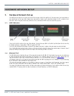
If you are sure you want to factory reset, hold down the RESET button near the RJ45 port for at least 10 seconds. The yellow
COMM LED will be solid-on during this time, and once it turns off you can release the button and the reboot process will
begin.


