FRONT PANEL LCD DISPLAY
TranScend Chassis – Operation Manual
4-9
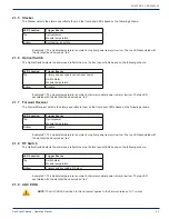
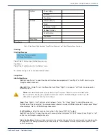
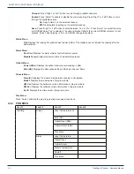
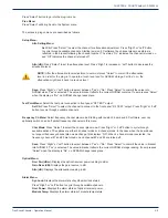
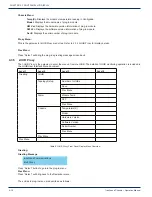
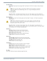
Press “Select” button to go into the plug-in menu.
Prev Menu:
Press “Select” will bring back to the System menu.
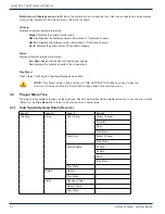
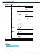
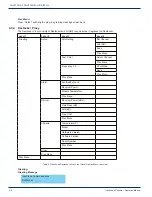
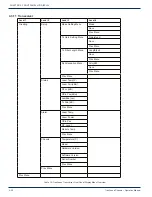
The entries in plug-in menu are described as follows:
Setup Menu:
Attn Setting Menu:
Sel Ch:
Press “Select” to select the channel for attenuation adjustment. Press “Right” or “Left” button
to cycle through available channels. Starting revision 2.C software, the channel plan mode status is
refl ected in the bracket following the channel number. The status “On” indicates the channel is turned on
and “Off” indicates the channel is turned off.
Attn (dB):
Press “Select” to set the attenuation level. Press “Right” to increase or “Left” button to decrease the
attenuation level.
NOTE: After the attenuation level adjustment, user must press “Select” to commit the attenuation
level in order for the plug-in to operate at such level and for NVRAM storage. Fail to do so, the
attenuation might revert back to previous level.
Save:
Press “Right” or “Left” button to select between “Yes” or “No”. Press “Select” to commit the value into
NVRAM when “Yes” is selected. The value in bracket refl ects the current NVRAM contetns. If user presses “Select”
when the display is “No”, no NVRAM change takes place.
Test Point Menu:
Select the test point connection to front panel “RF TEST” output.
Sel Ch:
Press “Select” to select the channel to connect to the front panel “RF TEST” output. Press “Right” or “Left”
button to cycle through available channels.
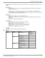
Frequency Ch Menu:
Select frequency channel plan mode. Starting with revision 3 board and 2.C software, user can
optionally switch on and off partial frequency channels via this menu.
Chnl Mode:
Press “Select” to select the channel plan mode. Press “Right” or “Left” button to cycle through
available options. The options are either 2-channel mode or 4-channel mode. In the case when the board does
not support frequency channel plan mode change, this displays “NA”. When 2-channel mode is selected, the
frequency channel #1 and #3 are turned on and channel #2 and #4 are turned off.
Save:
Press “Right” or “Left” button to select between “Yes” or “No”. Press “Select” to commit the value in bracket
into NVRAM if “Yes” is selected. The value in bracket refl ects the current NVRAM storage reading. If user presses
“Select” when the display is “No”, no NVRAM change takes place.
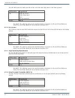
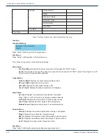
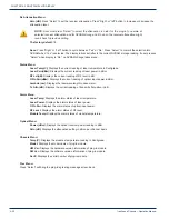
Optical Menu:
Rcvr Pwr (dBm):
Displays the optical receiver power reading in dBm.
Gain Resv (dB):
Displays the gain reserve in dB.
Attn (dB):
Displays the attenuation reading in dB.
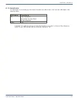
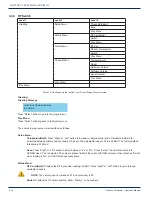
Alarm Menu:
Syn Lock:
Displays the alarm state of synthesizer lock status.
Press “Right” or “Left” button to cycle through available channels.
Rcvr Power:
Displays the alarm status of optical receiver power.
Module Temp:
Displays the alarm status of module temperature.
CHAPTER 4:

