LED DISPLAY
TranScend Chassis – Operation Manual
2-1
LED DISPLAY
2. LED Display
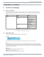
There are nine front panel LEDs, one indicates the chassis power supply status and four sets of two each indicate the status
of the four plug-in units. The number labeled on the front panel correspond to the slot identification; one on the most left and
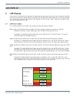
four on the most right (closest to power switch) when facing the rear of the chassis. Figure 1 below shows the generic alarm
table and corresponding color codes.
2.1 LED Color Codes
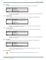
There are four possible colors of LEDs. They are observed during the following conditions.
Off:
indicates the monitored function is unavailable. This is also observed temporarily during power on LED test.
Example #1: Only slot 1 and slot 2 have plug in units. The LEDs for slot 3 and slot 4 are off.
Example #2: The High Sensitivity Quad Return Receiver is detected in slot 1; the RF LED for slot 1 is turned off
since RF detection is not available in this unit.
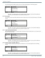
Green:
indicates the monitored function is healthy. This is also temporarily observed during power on LED test.
Example #1: The High Sensitivity Quad Return Receiver is detected in slot 1, and the OPT LED for slot 1 is green
which indicates the monitored level of all four optical power receivers in slot 1 are within normal operating range.
Amber:
indicates the monitored function is in minor alarm condition. This is also temporarily observed during power on LED
test.
Example #1: The High Sensitivity Quad Return Receiver is detected in slot 1, and the OPT LED for slot 1 is amber
which indicates the level of any one or more of the four optical power receivers in slot 1 are in minor alarm range.
The minor alarm is triggered if the monitored level is between the high and high-high or low and low-low thresholds.
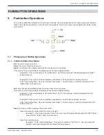
Red:
indicates the monitored function is in major alarm condition. This is also observed temporarily during power on LED
test.
Example #1:The High Sensitivity Quad Return Receiver is detected in slot 1, and the OPT LED for slot 1 is red
which indicates the level of any of the four optical power receivers in slot 1 are within major alarm range. The major
alarm is triggered if the monitored level is beyond the high-high or low-low thresholds.
Figure 1: Generic Alarm & LED Table Plug-in LED Definitions
CHAPTER 2:
Red
Red
Major/Low-Low
Minor/Low
Minor/High
Nominal
Major/High-High
Amber
Amber
Green


