LED DISPLAY
TranScend Chassis – Operation Manual
2-3
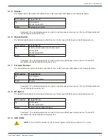
2.1.5 Stacker
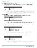
The Stacker detects the alarms and refl ects them on the front panel LEDs based on the following schema.
LED Location
Trigger Events
Top
Optical power
Module temperature
Bottom
Synthesizer lock state
Example #1: The module temperature is normal, but optical power is major low low. The top LED associated with
the slot shall be observed as “red”.
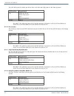
2.1.6 Optical Switch
The Optical Switch detects the alarms and refl ects them on the front panel LEDs based on the following schema.
LED Location
Trigger Events
Top
Primary and secondary optical input power
Switch alarm
Module temperature
Bottom
Disable
Example #1: The module temperature is normal, but primary optical power is major low low. The top LED
associated with the slot shall be observed as “red”.
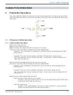
2.1.7 Forward Receiver
The Forward Receicer detects the alarms and refl ects them on the front panel LEDs based on the following schema.
LED Location
Trigger Events
Top
Optical power
Module temperature
Bottom
Disable
Example #1: The module temperature is normal, but optical power is major low low. The top LED associated with
the slot shall be observed as “red”.
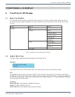
2.1.8 RF Switch
The Optical Switch detects the alarms and refl ects them on the front panel LEDs based on the following schema.
LED Location
Trigger Events
Top
Switch alarm
Module temperature
Bottom
Primary and secondary RF input
Example #1: The module temperature is normal, but primary optical power is major low low. The top LED
associated with the slot shall be observed as “red”.
2.1.9 AGC EDFA
NOTE: The AGC EDFA described in this document applies to the fi rmware release 1.21 or later.
CHAPTER 2:


