background image

4-6 

XDS-PRO (PRO1R, PRO4R & PRO1S, PRO4S) Satellite Receivers - User Guide  Rev. A  R830001-2106


RECEIVER WEB INTERFACE

ATX 

Confi dential & Proprietary

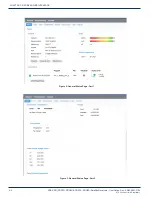
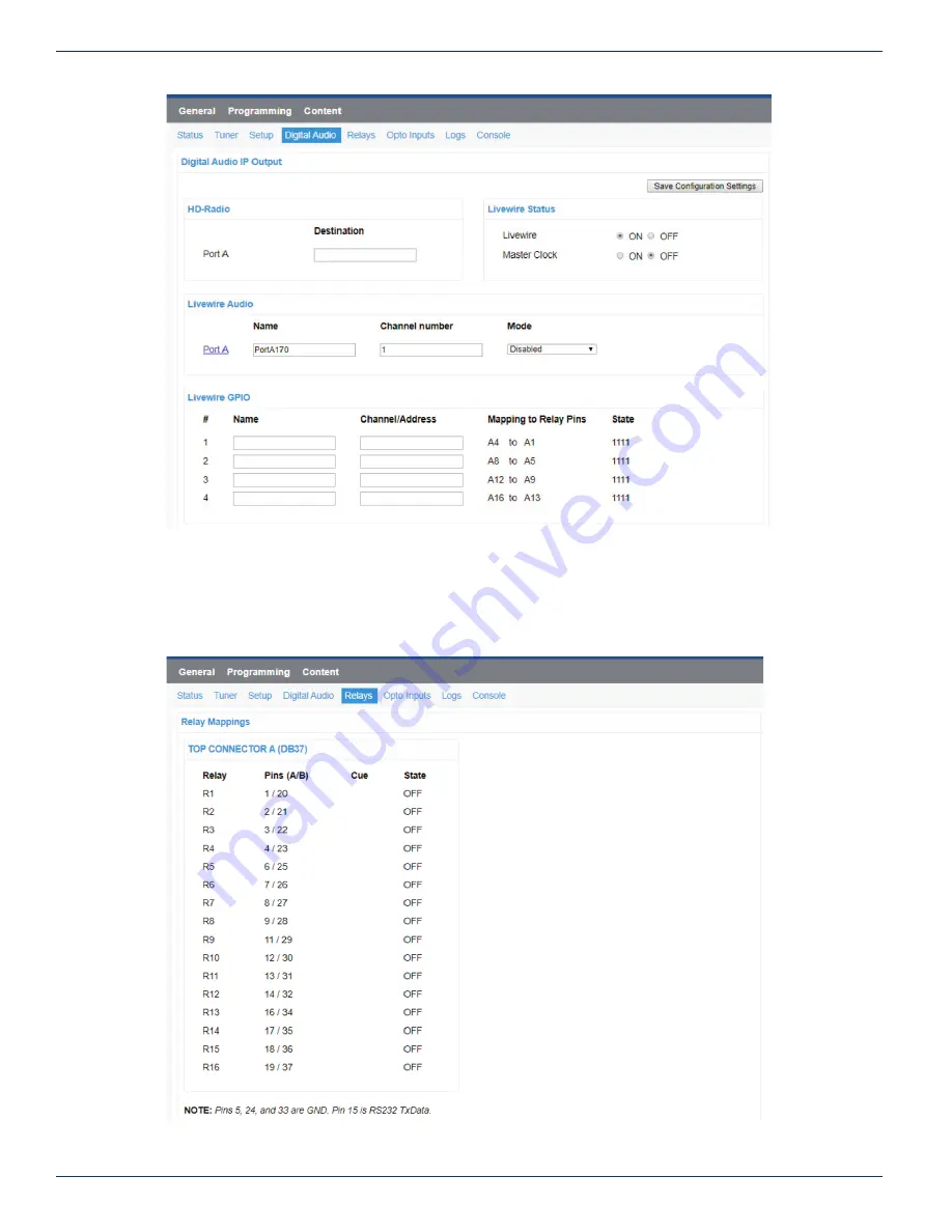
Figure 8: Digital Audio - Part 2

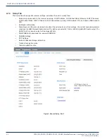
4.1.5  Relays Tab

The Relay Tab presents the user with cue to relay mappings that the receiver is assigned. Your network provides specifi c relay 

cue message than can be used to trigger a relay closure if the cue is mapped to a specifi c relay pin. These relay mappings are 

confi gured through the Affi liate Website.

Figure 9: Relay

CHAPTER  4:     

Summary of Contents for XDS-PRO Series

Page 1: ...USER GUIDE XDS PRO1R XDS PRO4R XDS PRO1S XDS PRO4S Receivers XDS PRO Series www atxnetworks com www atx com ...

Page 2: ...t to infringe Any terms mentioned or used that are known trademarks or service marks have been appropriately capitalized and italicized ATX Networks cannot attest to the accuracy of this information Use of a term in this document should not be regarded as affecting the validity of any trademark or service mark HD Radio Technology manufactured under license from iBiquity Digital Corporation U S and...

Page 3: ... 2 2 2 3 2 Uneven Loading of Rack 2 2 2 4 Connecting the Receiver to a Satellite Dish 2 2 2 4 1 Outdoor Antenna Grounding 2 2 2 4 2 DC Voltage Requirement 2 3 2 4 3 Warnings about Shorting DC 2 3 2 5 Connecting to the Ethernet Network 2 3 2 5 1 Connecting the Cables 2 4 2 5 2 Using DHCP or Static IP Addresses 2 4 2 5 3 Assigning a TCP IP Address 2 4 2 5 4 Assigning a Subnet Mask 2 4 2 5 5 Assignin...

Page 4: ...1 8 Console Tab 4 9 4 2 Programming Menu 4 9 4 2 1 Program Tab 4 9 4 2 2 Recordings Tab 4 9 4 3 Content Menu 4 10 4 3 1 Audio Tab 4 10 4 3 2 All Tab 4 10 4 4 XDS AMR Menu Optional 4 10 5 AFFILIATE WEB INTERFACE 5 1 5 1 Accessing and Loggin In 5 1 5 1 1 Obtaining Login Password for Receivers that are Equipped with Front Panels 5 1 5 1 2 Obtaining Login Password for Receivers that are NOT Equipped w...

Page 5: ...alog Audio Input 7 3 7 1 6 Digital Audio Input 7 3 7 1 7 Digital Audio Output 7 4 7 1 8 PAD ASYNC External Reset Port 7 4 7 2 Ethernet Port 7 5 7 3 RF Input Parameters 7 5 7 4 LBR Module Optional RF Input Parameters 7 6 7 5 Mechanical and Electrical 7 6 7 6 Environmental 7 6 8 REGULATORY COMPLIANCE 8 1 9 SERVICE SUPPORT 9 1 ...

Page 6: ...iv XDS PRO PRO1R PRO4R PRO1S PRO4S Satellite Receivers User Guide Rev A R830001 2106 ATX Confidential Proprietary This page left intentionally blank ...

Page 7: ...dio received via satellite on its single output port while the PRO1S and PRO4S can deliver up to four channels of audio on any one of its four balanced output ports Additionally content can be received and stored locally for later use This content can originate from a real time satellite broadcast from a high speed satellite IP distribution channel or can be retrieved via the Internet over the Eth...

Page 8: ...1 2 XDS PRO PRO1R PRO4R PRO1S PRO4S Satellite Receivers User Guide Rev A R830001 2106 INTRODUCTION ATX Confidential Proprietary CHAPTER 1 This page left intentionally blank ...

Page 9: ...nically controlled via temperature sensor This will allow the unit to operate under less than optimal conditions However once the receiver is located in a closed or rack environment the ambient temperature may be greater than room temperature Please take this into consideration when installing the receiver making sure that the ambient temperature around the receiver does not exceed the temperature...

Page 10: ...nical support Do not open the receiver as doing so will void the receiver s warranty 2 3 Physical Installation of the Receiver The following section will guide you through the physical installation of the XDS PRO receiver 2 3 1 Rack Mounting the Receiver The XDS PRO receiver has been specifically designed for installation and operation in an EIA standard 19 inch equipment rack When mounting it in ...

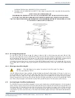
Page 11: ...e XDS PRO receiver In this case set the LNB Voltage setting to OFF 2 4 3 Warnings about Shorting DC Caution If the LNB Voltage mode is enabled be careful not to short the signal The voltage on this line is approximately 18V DC If the DC Voltage is shorted during installation transient voltage may damage the Demodulator In the case of a short over current protection circuitry will shut down the LNB...

Page 12: ...our purposes refer to section 3 2 2 1 2 5 5 Assigning a Default Gateway A gateway refers to a router or host which grants access to the internet If you have not enabled DHCP you must specify the TCP IP address of this default gateway To set this value refer to section 3 2 2 1 2 5 6 Proxy Server Configuration A proxy server can be configured through the front panel as detailed in section 3 3 3 1 or...

Page 13: ...ck Non associated cues will fire if they are mapped to a relay regardless of what program is playing All cues will be outputted through an RS 232 Tx pin on the receiver s relay port to be used by downstream systems 2 8 Connecting the Program Associated Data PAD Port The XDS PRO receivers are capable of receiving and displaying PAD in two different ways Your Network will provide baud rate settings ...

Page 14: ...2 6 XDS PRO PRO1R PRO4R PRO1S PRO4S Satellite Receivers User Guide Rev A R830001 2106 GETTING STARTED ATX Confidential Proprietary CHAPTER 2 This page left intentionally blank ...

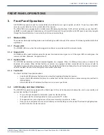
Page 15: ...The UPDATE led indicates a software download upgrade is in progress When it is blinking slowly once per second the download is in process When it blinks fast 3x per second an upgrade has been successful and the receiver should be rebooted at a convenient time when audio is off air The update LED will also be blinking if you haven t activated your receiver unit with the NMS See the Quick Start guid...

Page 16: ... Setup Tuner Setup M C Ports 115200 None 8 1 Setup Network DHCP ON Setup Network LAN1 Address 192 168 1 100 Setup Network LAN1 Subnet 255 255 255 0 Setup Network Gateway 192 168 1 1 Setup Network LAN3 Subnet 255 255 2550 Setup Network LAN2 Subnet 255 255 255 0 Setup Network DNS 1 3 192 168 1 1 DEL ADD Setup Network Proxy 192 168 1 2 80 Setup Network TEST NOC PING NOC ESC Setup Network NAS Setup US...

Page 17: ...e receiver FAULT HISTORY Offers a list of past faults which may have occurred Pushing 3 will clear the fault history ENVIRONMENT Indicates whether the internal fans are functioning inside the unit and the internal temperature of the receiver unit POWER STATUS Readings on the various voltage levels inside the receiver STORAGE STATUS Gives an indication of the internal storage drive usage in the rec...

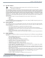
Page 18: ... to expose shared files and folders to other computers in the network can access To modify any of these numeric values use or to select which part of the IP to change Make a digit larger using and to make a digit smaller using Press SET whenever you are done editing and want to commit a setting 3 3 4 AUDIO PORTS Sub Menus From the Audio Ports sub menus users can change the settings for each of the...

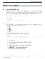
Page 19: ...information underneath the General button by default 4 1 General Menu The General menu lists most of the basic receiver attributes and settings After logging in you start in the General menu by default The tabs listed across the top for the General menu are Status Tuner Setup Relays Opto Inputs Logs Console The Status tab is the tab displayed by default upon entering the General menu 4 1 1 Status ...

Page 20: ...RO PRO1R PRO4R PRO1S PRO4S Satellite Receivers User Guide Rev A R830001 2106 ATX Confidential Proprietary RECEIVER WEB INTERFACE CHAPTER 4 Figure 2 General Status Page Part 1 Figure 3 General Status Page Part 2 ...

Page 21: ...Frequency Shows the actual locked frequency with offset The acquisition state of the tuner Eb N0 The energy per bit to noise power spectral density ratio it is a normalized signal to noise ratio measure also known as SNR per bit see Section 3 3 AGC A closed loop feedback regulation mechanism helps to equalize the average volume of different signals due to varying signal strength Fade count of the ...

Page 22: ...ss LAN3 Subnet Mask primary NMS website URL and backup NMS website URL Notification information Miscellaneous information including data about the serial ports and their settings the current hexadecimal alarm mask and the ASE3 Sample Rate selection The station can select 44 1KHz or 48KHz digital AES3 audio output The AES67 AoIP or Livewire output will be always 48KHz SNMP MIB link to download the ...

Page 23: ...ital Audio Tab The Digital Audio Tab presents the user with the capability to select Audio over IP AoIP options for AES67 or Livewire output It also has destination options for HD Radio E2X IP output that your network may send to directly feed an HD Radio exciter In Livewire mode the interface allows to enter Livewire GPIO configuration Figure 7 Digital Audio Part 1 CHAPTER 4 ...

Page 24: ...ital Audio Part 2 4 1 5 Relays Tab The Relay Tab presents the user with cue to relay mappings that the receiver is assigned Your network provides specific relay cue message than can be used to trigger a relay closure if the cue is mapped to a specific relay pin These relay mappings are configured through the Affiliate Website Figure 9 Relay CHAPTER 4 ...

Page 25: ... 4 1 6 1 Coded Opto Input Mode In this mode the receiver is expecting that there will be a closure in multiple Opto pins at a time and the combination of triggered pins can be can be programmed to a different function There are 16 possible combinations that the 4 Opto inputs can be triggered see Figure 10 Figure 10 Opto Inputs Coded 4 1 6 2 Uncoded Opto Input Mode In this mode the receiver is expe...

Page 26: ...per line in the commands window and press the SAVE button to save your Opto function You can use any receiver console command included in Section 6 2 Figure 12 Edit Opto Inputs 4 1 7 Logs Tab The Logs Tab presents the receiver activity logs It shows all core transactions the receiver is performing The user can select to display the logs in UTC or local time The user can download and save the logs ...

Page 27: ...and re broadcast 4 2 1 Programs Tab Each receiver is identified by the Network Management System NMS as authorized to receive and broadcast particular radio programs From the Programs tab you can see which programs the receiver is set up to receive and use In the Programs grid you are given the Program Name ID Code Mono Stereo Program ID PID Authorization status and the Port the current program is...

Page 28: ... which have been stored for later use by the receiver The file name along with download link ISCI code and received date are displayed The audio traffic and all tabs will all have the same layout 4 3 2 All Tab The All Tab displays all files which the receiver is currently storing Figure 17 Audio Content 4 4 XDS AMR Menu Optional Pressing the XDS AMR button will redirect you to the optional interna...

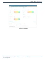
Page 29: ...XDS PRO PRO1R PRO4R PRO1S PRO4S Satellite Receivers User Guide Rev A R830001 2106 4 11 RECEIVER WEB INTERFACE ATX Confidential Proprietary Figure 18 XDS AMR Website CHAPTER 4 ...

Page 30: ...4 12 XDS PRO PRO1R PRO4R PRO1S PRO4S Satellite Receivers User Guide Rev A R830001 2106 RECEIVER WEB INTERFACE ATX Confidential Proprietary CHAPTER 4 This page left intentionally blank ...

Page 31: ...following section give instruction on the generic Affiliate Web Interface 5 1 Accessing and Logging In The website hosting your affiliate web page is provided by your broadcaster Please refer to the packaged Quick Start Guide and Network Data Sheet for instructions on navigating to this site After the page has loaded type the username which is your receiver s serial number available on the back pa...

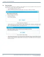
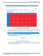
Page 32: ...tial Pop up Once the page loads you will be presented with a window asking which station schedule you would like to view or modify If the receiver is set up with more than one station the drop down menu can be used to navigate between them Once the desired station is shown in the window click OK Figure 21 Station Schedule Selection Once a station has been selected a grid of the current week s sche...

Page 33: ...ng which program to view The drop down menu will contain all of the programs for which the current station is authorized Once a program is selected press OK to view its network feeds Figure 23 Program Selection Drop Down Menus The next page will show the available network feeds for the selected program From here you can edit or delete a feed that is already scheduled by clicking on the correspondi...

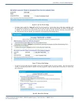
Page 34: ... Create a new link Figure 25 Scheduling Options If you are creating a new schedule and would like to play the network feed in its entirety leave the live option selected use the check boxes to select which days to play the feed specify a start and end date if desired and click the Add button at the bottom of the window To play only part of a live feed leave the top section on the live option and t...

Page 35: ...iginal feed to schedule the playback In addition to how many days to delay the feed you may also specify a custom start time and play only a partial feed as in the previous step except that you must start at the beginning of the delayed feed Figure 27 Delayed Feed Settings To capture a network feed for later playback select the record option from the top section As in the partial feed option you c...

Page 36: ...schedule will be updated as soon as possible You can then click on Calendar View to confirm the addition changes you ve made to the schedule Figure 30 Calendar View of Set Schedules To delete or modify an existing program in the schedule click on the text within the Calendar View tab to quickly link to the Network Feed page Modifications can be made by clicking the Edit button the changes will not...

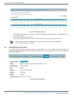
Page 37: ...flict is found a new window will appear where prioritization can be set for playback conflicts Figure 320 Prioritization Pop Up 5 3 Changing the Relay Mappings There are 32 different relays on the PRO4R and PRO4S receivers and 16 relays on the PRO1R and PRO1S receivers Each relay can correspond to a different net relay for a radio broadcast You can use the NMS to specify the relay mapping for the ...

Page 38: ... the changes you have made and to go back to the previous relay mapping click Cancel Note Net relays entered into the NMS s relay mappings text box bust be upper case alphanumeric i e only upper case letters or numbers 5 4 Checking Receiver Health The Affiliate website is capable of displaying the receiver s health status To view this navigate to the Health tab located on the top of the webpage Cl...

Page 39: ...Sheet Figure 36 XDS PRO Documentation 5 6 Changing the Receiver s Time Zone Using theAffiliate website it is also possible to change the receiver s time zone settings To do this navigate to the Configuration tab located on the top of the webpage There is a pulldown box that will configure the time zone of the receiver If you would like to observe daylight savings time indicate this using the check...

Page 40: ...5 10 XDS PRO PRO1R PRO4R PRO1S PRO4S Satellite Receivers User Guide Rev A R830001 2106 AFFILIATE WEB INTERFACE ATX Confidential Proprietary CHAPTER 5 This page left intentionally blank ...

Page 41: ...for flow control Press Apply and then press OK You are now ready to communicate with the XDS PRO receiver via the console you have created There are a variety of typed commands that the receiver responds to By default the console is not logged into the receiver and as such the console will have a very limited set of commands to use Without logging in the user can only use status commands and may n...

Page 42: ...t fan x to val percent x 0 X TACH Get fan x tach value x 0 Table 3 FAN Command FIRE Command Fire cues locally on the receiver Syntax is FIRE CUE e g C T01 or 2 PGM CODE HELP Command This command prints all of the commands available to the current profile There are no options for this command LCD Command The LCD command allows the user to display custom content on the front panel of the receiver Sy...

Page 43: ... all ports SYNC Sync audio ports to regular schedules PAUSE RESUME PREVIEW port TONE 100 1000 10000 STOP Stops programming and puts tone on all ports CRASH pgm LOCK UNLOCK Change to the requested program and optionally lock the port CRASH 0 Unlock the requested port and sync to regular schedule Table 6 PORT Command PING Command This command will attempt to ping the IP address specified by the argu...

Page 44: ...RM Command The ALARM command tells you and allows you to change the current ALARM mask the receiver is using To see the current ALARM mask without modifying it type ALARM without an argument following it To change the alarm mask type ALARM MASK where MASK is a hexadecimal digit in the range 0 FFFFFFFF Anything larger than FFFFFFFF will be interpreted as the largest mask FFFFFFFF ALIB Command Used ...

Page 45: ... reset Ethernet and Tuner parameters Using this command requires a receiver restart FIND Command See GREP Command FPGA Command FPGA diagnostics command Syntax FPGA LOAD filename GREP Command Unix command used to search log files Prints output containing specific pattern Syntax GREP pattern cmd I2C Command I2C Peripheral diagnostics Table 11 shows all I2C arguments Option Argument Action DEV ADDR v...

Page 46: ...y mail recipient name domain format limit 256 characters comma separate multiple addresses FROM originator Specify mail originator name domain format limit 64 characters ALERT hex Enable alerts on given status bits Table 15 MAIL Command MAINT Command Used to set and display the receiver s designated maintenance time window Option Argument Action SHOW Display maintenance window and occurrence CLEAR...

Page 47: ...d for specified port SHOW SCHED pgmid MONITOR ON OFF USBLOAD Enable PSI and PID monitoring CLEAR WIN GROUPS NIT pid In hex 0 auto from PAT SET pgmid pid Manually add a program PID pair to PSI ACTIVATE YES NO Table 20 PSI Command PLAY Command Used to play a file Syntax PLAY filename PWR Command Used to display power settings REBOOT Command The reboot command can take many different options Option A...

Page 48: ...mmand TTY Command Modem diagnostics command See Table 25 for usage Option Argument Action port 0 2 Open serial port 0 M C 1 NETCUE 2 MODEM port 2400 9600 19200 Set baud rate for specified port 8 data no parity 1 stop bit Table 25 TTY Command TUNER Command This command is used to view and modify all of the receiver s tuner settings Typing this command without any options will display a usage messag...

Page 49: ...r and Control Interface RS 232C compatible DB 9 female Web Interface Automatically broadcast via LAN and WAN Table 27 Interface Features 7 1 2 M C Interface Connector Pin Outs The Monitor and Control M C port allows basic configuration of the XDS PRO receiver via an asynchronous RS 232C electrical interface It uses the following protocol settings 115 2K bits per second 8 data bits No Parity 1 stop...

Page 50: ...s Specifications PIN FUNCTION PIN FUNCTION 1 RLY1A 20 RLY1B 2 RLY2A 21 RLY2B 3 RLY3A 22 RLY3B 4 RLY4A 23 RLY4B 5 Ground 24 Ground 6 RLY5A 25 RLY5B 7 RLY6A 26 RLY6B 8 RLY7A 27 RLY7B 9 RLY8A 28 RLY8B 10 Ground 29 RLY9B 11 RLY9A 30 RLY10B 12 RLY10A 31 RLY11B 13 RLY11A 32 RLY12B 14 RLY12A 33 Ground 15 TxData 34 RLY13B 16 RLY13A 35 RLY14B 17 RLY14A 36 RLY15B 18 RLY15A 37 RLY16B 19 RLY16A Table 31 Relay...

Page 51: ... 22max Table 34 Analog Audio Input Specifications PIN FUNCTION 1 L IN 2 Ground 3 Not Connected 4 Ground 5 R IN 6 L IN 7 Ground 8 Not Connected 9 R IN Table 35 Analog Audio Input Pin Out 7 1 6 Digital Audio Input In addition to the analog audio input the PRO4R and PRO4S receivers also have one digital audio input port that shares the same connector Table 36 provides the specification for digital au...

Page 52: ... output that matches the single analog audio output of the receiver Connector DB 9 Male Format Balanced AES EBU Table 38 Digital Audio Output Specifications PIN FUNCTION PRO1R PRO1S PRO4R PRO4S 1 CH0_TX CH0_TX 2 Not connected CH1_TX 3 Ground Ground 4 Not connected CH2_TX 5 Not connected CH3_TX 6 CH0_TX CH0_TX 7 Not connected CH1_TX 8 Not connected CH2_TX 9 Not connected CH3_TX Table 39 Digital Aud...

Page 53: ...nnection Rate 10 100Base TX Auto Number of Ports PRO1R PRO4S 2 PRO1S PRO4S 3 Max Output IP Rate Up to 20 Mbps combined for all ports VLAN Each port is managed for VLAN use Table 429 Ethernet Port 7 3 RF Input Parameters A DVS S modulated satellite signal will be received and demodulated by the XDS PRO receiver Input signal and connector specifications are provided in Table 43 By default TUNER 1 co...

Page 54: ...te 100 KSPS to 40 MSPS DVB S2 QPSK Symbol rate 1oo KSPS to 40 MSPS DVB S2 8PSK Symbol rate 1 to 40 MSPS Modulation Scheme QPSK DVB S or DVB S2 8PSK DVB S2 Forward Error Correction modes Reed Solomon and Viterbi DVB S MX3 LDPC and BCH normal frames DVB S2 LNB Power 18 VDC 500 mA MAX Table 44 LBR Module RF Input Parameters 7 5 Mechanical and Electrical The XDS PRO receiver chassis specifications are...

Page 55: ...NCLUDING INTERFERENCE THAT MAY CAUSE UNDESIRED OPERATION North America Safety UL 60950 1 2012 R 2011 12 CAN CSA C22 2 No 60950 1 2012 A1 2011 Europe Emissions THE XDS PRO WAS TESTED ACCORDING TO THE REQUIREMENTS OF THE EMC DIRECTIVE 89 336 EEC AND LOW VOLTAGE DIRECTIVE 73 23 EEC AND COMPLIES WITH ALL THE REQUIREMENTS FOR THE CE MARKING THE XDS PRO RECEIVER IS PRODUCTION MONITORED BY TUV SÜD AMERIC...

Page 56: ...8 2 XDS PRO PRO1R PRO4R PRO1S PRO4S Satellite Receivers User Guide Rev A R830001 2106 REGULATORY COMPLIANCE ATX Confidential Proprietary CHAPTER 8 This page left intentionally blank ...

Page 57: ...mber for any ATX products that require service and are in or out of warranty before returning a failed module to ATX TECHNICAL SUPPORT Tel 289 204 7800 press 1 Toll Free 866 YOUR ATX 866 968 7289 USA Canada only Email support atx com SALES ASSISTANCE Tel 289 204 7800 press 2 Toll Free 866 YOUR ATX 866 968 7289 USA Canada only Email insidesales atx com FOR HELP WITH AN EXISTING ORDER Tel 289 204 78...

Page 58: ...l 289 204 7800 Toll Free 866 YOUR ATX 866 968 7289 support atx com 2019 by ATX Networks Corp and its affiliates collectively ATX Networks Corp All rights reserved This material may not be published broadcast rewritten or redistributed Information in this document is subject to change without notice ...

Reviews: