background image

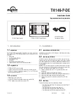
TH146-P-DE 

      400-280-004-C                    11/29/06                    6/9

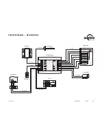
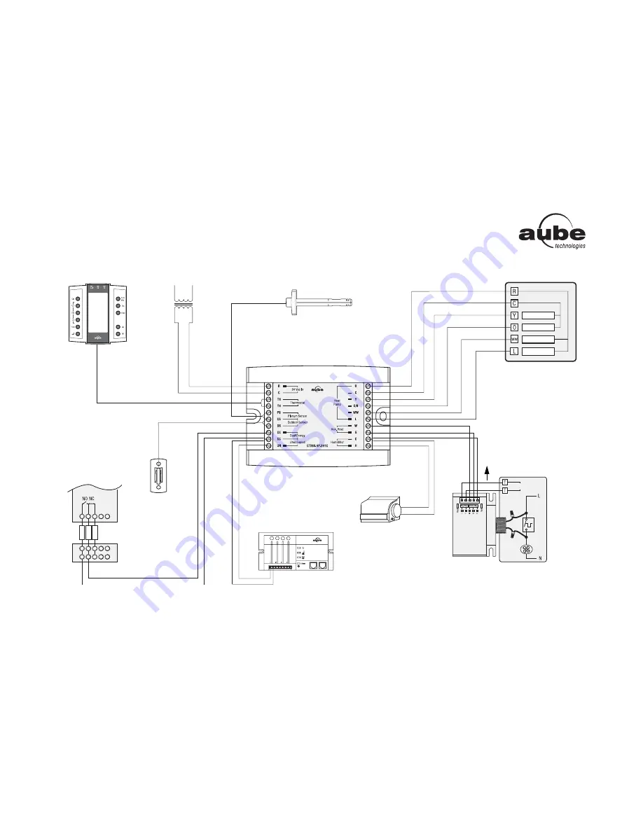
Connection Diagram — Add-on Installation

TH146-P

24 V Transformer

Dual Energy

AC144-03

AC146-410

CT241

RC845

Humidifier

Auxiliary
Heating
System

Heat Pump

Compressor

Defrost

Fault

Furnace

Fan Limit

CT280-HP-2H1C

Ye

llo

w

Re

d

Gree

n

Reversing Valve

16 - 22 AWG

16 - 18 AWG

16 - 22 AWG

16 - 18 AWG

16 - 22 AWG

16 - 18 AWG

16 - 22 AWG

16 - 18 AWG

16 - 22 AWG

16 - 22 AWG

Summary of Contents for TH146-P-DE

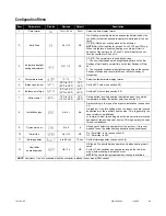
Page 1: ...or air outlet or stagnant air behind a door Do not install the console on a wall hiding air ducts nor expose it to direct sunlight NOTE If this controller replaces an existing thermostat the wires tha...

Page 2: ...oller terminals PS and CS no polarity For more information refer to the instructions provided with the sen sor NOTE The maximum wire length is 30 m 100 feet The dual energy input can be connected to t...

Page 3: ...utdoor temperature is above the balance point high bP H the auxiliary heat is disabled see page 4 item 6 and only the heat pump can be used NOTE Balance points will not work if the AC144 03 outdoor te...

Page 4: ...point high 5 C to 30 C 23 F to 86 F 5 C 41 F Set the bP H value see section 4 2 7 Defrost point 10 C to 15 C 14 F to 59 F 10 C 50 F During defrost auxiliary heating is activated when the outside temp...

Page 5: ...ion Diagram New Installation TH146 P AC144 03 AC146 410 CT241 Humidifier Heat Pump Compressor Fault CT280 HP 2H1C Fan Auxiliary Heat Defrost Valve Dual Energy 16 22 AWG 16 22 AWG 16 22 AWG 16 22 AWG 1...

Page 6: ...Transformer Dual Energy AC144 03 AC146 410 CT241 RC845 Humidifier Auxiliary Heating System Heat Pump Compressor Defrost Fault Furnace Fan Limit CT280 HP 2H1C Yellow Red Green Reversing Valve 16 22 AWG...

Page 7: ...n Program clear Humidity setting Return Temperature adjustment mode selection Fan operating mode selection System operating mode selection Up Down buttons Indicator LEDs FAULT System fault EH Emergenc...

Page 8: ...days are selected they will all now have the same settings for period 2 To set the start time of a period first press Pgm until the period number P1 to P4 is displayed and the time display flashes The...

Page 9: ...rchase by the consumer If at any time during the warranty period the product is determined to be defective or malfunctions Aube shall repair or replace it at Aube s option If the product is defective...

Reviews: