AUBER INSTRUMENTS
WWW.AUBERINS.COM
2015.04
P4/4
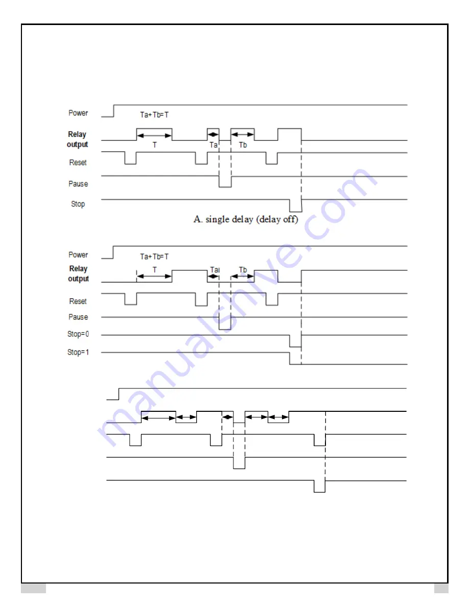
8. Timing Diagrams
Following diagrams show relay output ON/OFF time under different relay output modes and operating function modes. Please note: 1) “RUN” is set to “rSt” in
following examples, powering up to start the timer is not discussed here. 2) Timer starts counting from the moment when reset key/switch is released or input (TTL)
signal is from low to high. 3) Timer display stops counting as soon as stop key/ switch is pressed (from high to low), but relay output will only be triggered when stop
key/switch is released (from low to high).
B. single delay (delay on) (for stop function please see note 2 on page 5/5 for details)
Power
Relay
output
Reset
Pause
Stop
T1
Ta
Tb
Ta+Tb=T1
T2
T2
C. delay interval (delay on)


