V4.5
©2015-2019 AUBO.All rights reserved.
33
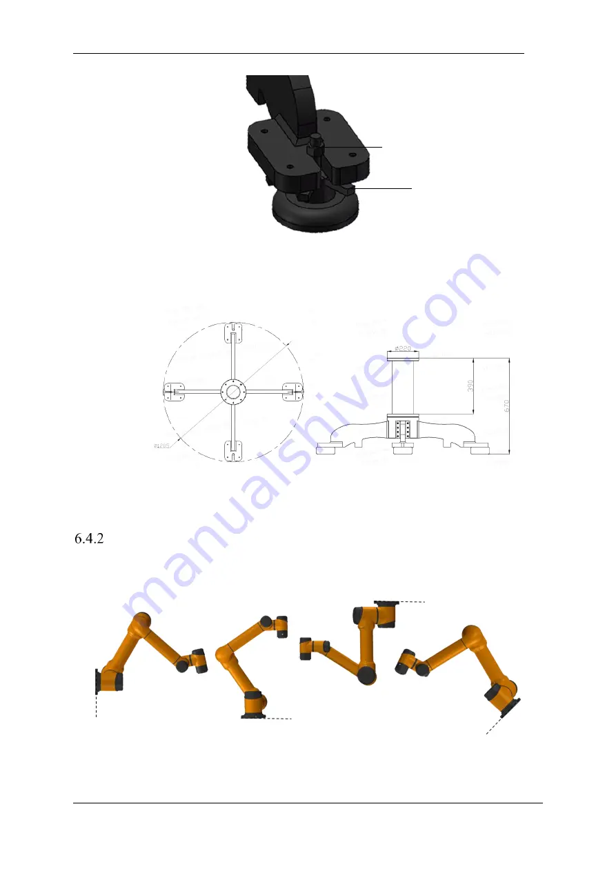
Figure 6-3
Diagram of manipulator base structur
e
The mechanical dimensions of the manipulator base structure are shown in Figure 6.4
Figure 6-4 Mechanical dimensions of the manipulator base structure (left: plan view; right: front view)
Manipulator Installation
The robot has a function of self-adaption for Installation pose. It can be installed in base, hoisting, mount on
wall or any specific installation method, as shown below:
Figure 6-5 Diagram of different installation poses
Using four M8 bolts to fix manipulator on the base. It’s recommend using two -6mm holes to install pins
to improve the installation accuracy. Mechanical dimensions is shown in Figure 6.6.
Nut
Plum blossom wheel
Summary of Contents for AUBO-i10
Page 1: ...USER MANUAL AUBO i10 CB4 Please read this manual carefully before using the product...
Page 2: ......
Page 10: ...V4 5 2015 2019 AUBO All rights reserved vi...
Page 26: ...V4 5 2015 2019 AUBO All rights reserved 22...
Page 44: ...V4 5 2015 2019 AUBO All rights reserved 40...
Page 56: ...V4 5 2015 2019 AUBO All rights reserved 52...
Page 87: ...V4 5 2015 2019 AUBO All rights reserved 83...
Page 127: ...V4 5 2015 2019 AUBO All rights reserved 123...
Page 161: ...V4 5 2015 2019 AUBO All rights reserved 157 Figure 11 43 script file editor...
Page 179: ......


