V4.5
©2015-2019 AUBO.All rights reserved.
74
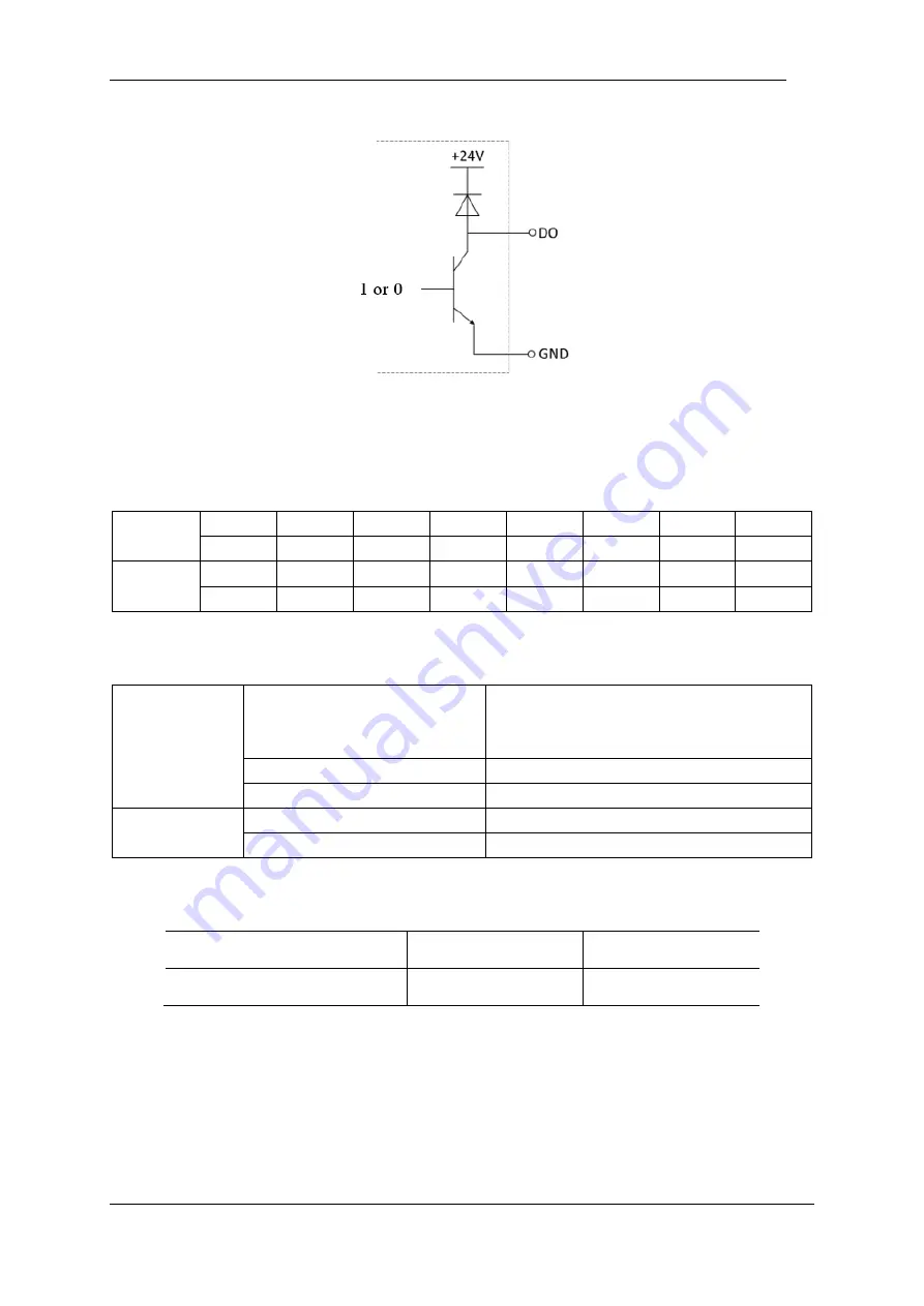
Figure 8-20 DO connect GND
The DO end can be directly connected to the load or communicate with a PLC or other robot.
The user can control the above digital IO through the teach pendant AUBORPE software.
Input
DI00
DI01
DI02
DI03
DI04
DI05
DI06
DI07
DI10
DI11
DI12
DI13
DI14
DI15
DI16
DI17
Output
DO00
DO01
DO02
DO03
DO04
DO05
DO06
DO07
DO10
DO11
DO12
DO13
DO14
DO15
DO16
DO17
Electrical parameter specification
DI
Input form
P-lesend
No-voltage contact input
NPN open collector transistor
Input method
Input signal current
Electrical specifications
5mA/DC24V
DO
Output form
Transistor (P-lesend type)
Electrical specifications
300mA/DC24V
Electrical parameters
Parameter term
minimum value
Maximum value
Single DI input voltage
0 V
24 V
Example
Some common wiring examples are listed below.
DI end connection button switch
As shown in the figure below, the DI terminal can be connected to ground (G) through a normally open
Summary of Contents for AUBO-i10
Page 1: ...USER MANUAL AUBO i10 CB4 Please read this manual carefully before using the product...
Page 2: ......
Page 10: ...V4 5 2015 2019 AUBO All rights reserved vi...
Page 26: ...V4 5 2015 2019 AUBO All rights reserved 22...
Page 44: ...V4 5 2015 2019 AUBO All rights reserved 40...
Page 56: ...V4 5 2015 2019 AUBO All rights reserved 52...
Page 87: ...V4 5 2015 2019 AUBO All rights reserved 83...
Page 127: ...V4 5 2015 2019 AUBO All rights reserved 123...
Page 161: ...V4 5 2015 2019 AUBO All rights reserved 157 Figure 11 43 script file editor...
Page 179: ......


