V4.5
©2015-2019 AUBO.All rights reserved.
76
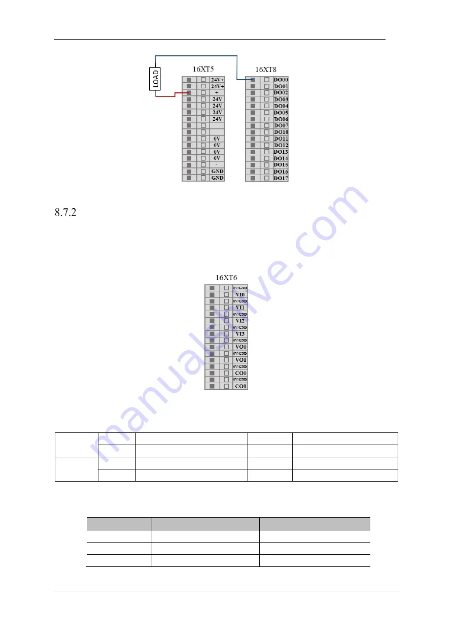
Figure 8-23 DO connect to load
Analog I/O interface
The analog I/O interface is located on the interface board on the back of the control box. There are 4 pairs
of analog voltage input interfaces, indicated by VI. There are 2 analog voltage outputs and 2 analog current
outputs, which are represented by VO and CO respectively. As shown below.
Figure 8-24 Analog I/O interface diagram
General purpose analog input and output available to users
Input
VI0
Analog voltage input
VI2
Analog voltage input
VI1
Analog voltage input
VI3
Analog voltage input
Output
VO0
Analog voltage output
CO0
Analog current output
VO1
Analog voltage output
CO1
Analog current output
General purpose analog input and output interface electrical parameter specifications available to
users
Type
voltage
current
Input
0~+10V
-
Output
0~+10V
0~20mA
Accuracy
±1%
±1%
Summary of Contents for AUBO-i10
Page 1: ...USER MANUAL AUBO i10 CB4 Please read this manual carefully before using the product...
Page 2: ......
Page 10: ...V4 5 2015 2019 AUBO All rights reserved vi...
Page 26: ...V4 5 2015 2019 AUBO All rights reserved 22...
Page 44: ...V4 5 2015 2019 AUBO All rights reserved 40...
Page 56: ...V4 5 2015 2019 AUBO All rights reserved 52...
Page 87: ...V4 5 2015 2019 AUBO All rights reserved 83...
Page 127: ...V4 5 2015 2019 AUBO All rights reserved 123...
Page 161: ...V4 5 2015 2019 AUBO All rights reserved 157 Figure 11 43 script file editor...
Page 179: ......


