background image

OPERATION 


Page 52 

MVS User Manual 

710-13019-00A 


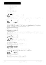
Motor temperature 


Current 


Motor power 


Voltage 


Last start information 


Date and time 


Performance graphs 


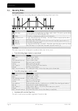
SCR conduction 


NOTE 

Screens shown here are with the default settings. 


Starter Status 

The starter status screen shows details of the starter's operating status, including motor current, power and temperature.. 

 0A 
Ready 
M1 000% 


00000kW 


Programmable screen 

The MVS's user-programmable screen can be configured to show the most important information for the particular 
application.    Use parameters 8E to 8H to select which information to display.     


 0A 
Ready  

0A 

00000 kWh   

00000hrs 


Motor Temperature 

The temperature screen shows which motor data set is in use, and the temperature of the motors as a percentage of total 
thermal capacity. 

 0A 
Primary Motor Set 

M1 000%   

M2 000% 


NOTE 

M2 xxx% temperature is not applicable to this product. 


Current monitoring screen 

The current screen shows real-time line current on each phase. 


 0A 
Phase currents (Gnd Crnt XX.XA) 
0000A 0000A  0000A 


Motor Power 

The motor power screen shows motor power (kW, HP and kVA) and power factor. 

 0A 
00000kW   00000HP 
00000kVA   

-. - - pf 


Voltage 

The voltage screen shows real-time line voltage across each phase. 

Summary of Contents for MVS

Page 1: ......

Page 2: ...ing 14 4 7 Terminal Block Controller 15 4 8 Power Circuits 15 4 9 Internal Wiring 18 Section 5 Keypad and Feedback 19 5 1 The Controller 19 5 2 Displays 19 5 3 Menus 19 Section 6 Programming Menu 22 6 1 Standard Menu 22 6 2 Extended Menu 23 6 3 Load Save Settings 26 6 4 Parameter Descriptions 26 Section 7 Commissioning 41 7 1 Commissioning Menu 41 7 2 Low Voltage Test Mode 44 Section 8 Maintenance...

Page 3: ...CONTENTS Page 2 MVS User Manual 710 13019 00A Section 11 Appendix 59 11 1 Parameter Record 59 11 2 Accessories 61 11 3 Maintenance 64 ...

Page 4: ...ntacts or switches operating the control inputs must be suitable for low voltage low current switching ie gold flash or similar Cables to the control inputs must be segregated from mains voltage and motor cabling Some electronic contactor coils are not suitable for direct switching with PCB mount relays Consult the contactor manufacturer supplier to confirm suitability The examples and diagrams in...

Page 5: ...o avoid exposure of the electronics to cement and or concrete dust 2011 AuCom Electronics Ltd All Rights Reserved As AuCom is continuously improving its products it reserves the right to modify or change the specification of its products at any time without notice The text diagrams images and any other literary or artistic works appearing in this document are protected by copyright Users may copy ...

Page 6: ...List Starting Constant current Current ramp Stopping Coast to stop Soft stop Protection Under Overvoltage Mains frequency Phase sequence Shorted SCR Motor overload thermal model Instantaneous overcurrent two stages Time overcurrent Ground fault Undercurrent Current imbalance Motor thermistor Excess start time Power circuit Auxiliary trip Extensive input and output options Remote control inputs 3 x...

Page 7: ... motor can successfully complete a start The MVS uses information from previous starts to calculate the motor s available thermal capacity and will only permit a start which is predicted to succeed This feature can be enabled or disabled using parameter 4N Motor Temperature Check Comprehensive Event and Trip Logging The MVS has a 99 place event log to record information on soft starter operation A...

Page 8: ...c 220 240 Vac Supply Voltage V02 2300 Vac 50 60 Hz V03 3300 Vac 50 60 Hz V04 4160 Vac 50 60 Hz V06 6600 Vac 50 60 Hz V07 7200 Vac 50 60 Hz Current Rating 0080 80 A AC53b 4 20 1780 0159 159 A AC53b 4 20 1780 0230 230 A AC53b 4 20 1780 0321 321 A AC53b 4 20 1780 0500 500 A AC53b 4 20 1780 0600 600 A AC53b 4 20 1780 ...

Page 9: ...models with current ratings of 500 and 600 A the MVSxxxx V06 dimensions apply NOTE In addition to the dimensions of the soft starter power assembly an enclosure must allow space for the following required components MVS soft starters must always be installed with a main contactor and bypass contactor Models with current ratings 500 A and above require forced air ventilation when installed in an en...

Page 10: ...06 6 6 kV Phase phase MVSxxxx V07 7 2 kV Phase phase Rated Frequency fr 50 60 Hz Rated lightning impulse withstand voltage Up MVSxxxx V02 04 45 kV MVSxxxx V06 V07 45 kV Rated power frequency withstand voltage Ud MVSxxxx V02 V04 11 5 kV MVSxxxx V06 V07 20 kV Rated normal current lr MVS0080 Vxx 80 A MVS0159 Vxx 159 A MVS0230 Vxx 230 A MVS0321 Vxx 321 A MVS0500 Vxx 500 A MVS0600 Vxx 600 A Rated short...

Page 11: ... 5 to 95 Relative Humidity Pollution Degree Pollution Degree 3 Vibration Designed to IEC 60068 EMC Emission Equipment Class EMC Class A Conducted Radio Frequency Emission 10 kHz to 150 kHz 120 69 dB µV 0 15 MHz to 0 5 MHz 79 dB µV 0 5 MHz to 30 MHz 73 dB µV Radiated Radio Frequency Emission 0 15 MHz to 30 MHz 80 50 dB µV m 30 MHz to 100 MHz 60 54 dB µV m 100 MHz to 2000 MHz 54 dB µV m This product...

Page 12: ...earance is required below or at the sides The power assembly should be installed with 100 mm clearance above for isolation NOTE Models with current ratings 500 A and above require forced air ventilation when installed in an enclosure Mounting Points The power assembly is mounted in place using four M12 bolts One bolt is required through each corner at the base of the unit tightened to a torque of ...

Page 13: ...ion If you intend to use a communication module allow for a minimum clearance of 120 mm behind the mounting panel Drill 5 mm holes to accommodate the studs on the controller Fit the controller through the cutout and tighten the nuts onto the studs NOTE Before installation always ensure that you are using the correct controller for the soft starter This can be checked by comparing the serial number...

Page 14: ...mm inch mm inch mm inch mm inch mm inch MVSxxxx V02 228 8 98 79 3 11 744 29 29 79 3 11 129 5 08 179 7 05 200 7 87 200 7 87 200 7 87 MVSxxxx V03 MVSxxxx V04 MVSxxxx V06 228 8 98 79 3 11 804 31 65 107 4 19 164 6 46 222 8 72 268 10 55 268 10 55 268 10 55 MVSxxxx V07 For models MVSxxxx V02 to MVSxxxx V04 these dimensions apply up to 321 A For the same models with current ratings of 500 and 600 A the M...

Page 15: ...led in three ways using the buttons on the Controller via remote inputs via a serial communication link The LCL RMT button controls whether the MVS will respond to local control via the Controller or remote control via the remote inputs The Local LED on the Controller is on when the soft starter is in local control mode and off when the soft starter is in remote control mode Control via the serial...

Page 16: ...nsient overvoltage protection MV LV control supply transformer Main Contactor The MVS must always be installed with a main contactor Select a contactor with an AC3 rating greater than or equal to the full load current rating of the connected motor or there is an option for a circuit breaker above 7 2 kV The main contactor is associated with terminals L1 L2 L3 on the supply side of the soft starter...

Page 17: ...coil is associated with output terminals 23 24 and the auxiliary Normally Open contact is associated with input terminals C73 C74 of the soft starter refer to Power Circuit Configuration To ensure that the potentially dangerous medium voltage area is isolated from the low voltage control area power is supplied to the bypass contactor coil from the control voltage terminal block refer to Internal W...

Page 18: ...s contactor external C53 C54 Programmable input A 2 To motor C63 C64 Programmable input B A2 Control voltage terminals 6 Programmable outputs 3 Control supply 43 44 Programmable Relay output A A3 Power interface PCB 51 52 54 Programmable Relay output B 4 Relay outputs 61 62 64 Programmable Relay output C C73 C74 Bypass contactor feedback signal 7 Motor thermistor input 13 14 Main contactor KM1 8 A...

Page 19: ...lied but must be connected at site 2 Feed connected to A1 or A3 must be externally fused A5 Gate drive PCBs NOTE The control voltage terminal section A2 has links fitted for 110 VAC external control and contactor coil voltages For other voltages remove these links and refit as indicated External control supply Contactor coil supply KM1 KM3 Voltage Connect into Link from Voltage Link from 110 VAC A...

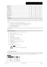
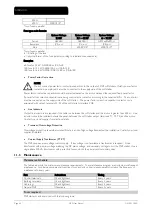
Page 20: ... current or motor power as selected in parameter 8D Use the and buttons to select the information shown on the bottom half of the screen Starter status User programmable screen Motor temperature Current Motor power Voltage Last start information Date and time Performance graphs SCR conduction Refer to Operating feedback on page 51 for further details 5 3 Menus Commissioning Menu The Commissioning ...

Page 21: ...he parameter setting use the and buttons Pressing or once will increase or decrease the value by one unit If the button is held for longer than five seconds the value will increase or decrease at a faster rate to save changes press STORE The setting shown on the display will be saved and the Controller will return to the parameter list to cancel changes press EXIT The Controller will ask for confi...

Page 22: ...K 710 13019 00A MVS User Manual Page 21 Logs Menu The Logs Menu provides information on events trips and starter performance To open the Logs Menu press ALT then F1 LOGS Refer to Logs Menu on page 45 for further details ...

Page 23: ...rameters allowing the user to configure the MVS as required for the application For details of individual parameters refer to Parameter Descriptions on page 26 1 Motor Data 1 1A Motor Full Load Current 2 Start Stop Modes 1 2A Start Mode 2B Start Ramp Time 2C Initial Current 2D Current Limit 2H Stop Mode 2I Stop Time 3 Auto Start Stop 3C Auto Stop Type 3D Auto Stop Time 4 Protection 4A Excess Start...

Page 24: ...Ramp Time 2C Initial Current 2D Current Limit 2E Reserved 2F Kickstart Time 2G Kickstart Level 2H Stop Mode 2I Stop Time 3 Auto Start Stop 3A Reserved 3B Reserved 3C Auto Stop Type 3D Auto Stop Time 4 Protection 4A Excess Start Time 4B Excess Start Time 2 4C Undercurrent 4D Undercurrent Delay 4E Instantaneous Overcurrent 4F Instantaneous Overcurrent Delay 4G Phase Sequence 4H Current Imbalance 4I ...

Page 25: ...ay 7C Relay A Off Delay 7D Relay B Function 7E Relay B On Delay 7F Relay B Off Delay 7G Relay C Function 7H Relay C On Delay 7I Relay C Off Delay 7J Reserved 7K Reserved 7L Reserved 7M Low Current Flag 7N High Current Flag 7O Motor Temperature Flag 7P Analog Output A 7Q Analog A Scale 7R Analog A Maximum Adjustment 7S Analog A Minimum Adjustment 7T Reserved 7U Reserved 7V Reserved 7W Reserved 8 Di...

Page 26: ...ved 11A Reserved 12 Slip Ring Motors 12A Motor Data 1 Ramp 12B Motor Data 2 Ramp 12C Changeover Time 12D Slip Ring Retard 15 Advanced 15A Access Code 15B Adjustment Lock 15C Emergency Run 16 Protection Action 16A Motor Overload 16B Excess Start Time 16C Undercurrent 16D Instantaneous Overcurrent 16E Current Imbalance 16F Frequency 16G Input A Trip 16H Input B Trip 16I Motor Thermistor 16J Starter ...

Page 27: ...tarter to match the connected motor These parameters describe the motor s operating characteristics and allow the soft starter to model the motor s temperature 1A Motor FLC Range 5 1000A Default 100A Description Matches the starter to the connected motor s full load current Set to the full load current FLC rating shown on the motor nameplate 1B Locked Rotor Time Range 0 01 2 00 minutes seconds Def...

Page 28: ...l torque before using this feature 2H Stop Mode Options Coast To Stop Default TVR Soft Stop Description Selects the stop mode 2I Stop Time Range 0 00 4 00 minutes seconds Default 0 seconds Description Sets the time for soft stopping the motor using timed voltage ramp If a main contactor is installed the contactor must remain closed until the end of the stop time 3 Auto Stop The MVS can be programm...

Page 29: ...below a specified level while the motor is running Parameter 4C Undercurrent Range 0 100 Default 20 Description Sets the trip point for undercurrent protection as a percentage of motor full load current Set to a level between the motor s normal working range and the motor s magnetising no load current typically 25 to 35 of full load current A setting of 0 disables undercurrent protection Parameter...

Page 30: ...ft starter s tolerance for frequency variation Parameter 4L Frequency Delay Range 0 01 4 00 minutes seconds Default 1 second Description Slows the MVS s response to frequency disturbances avoiding trips due to momentary fluctuations NOTE If the mains frequency drops below 35 Hz or rises above 75 Hz the starter will trip immediately irrespective of the settings for Frequency Trip parameters 4M Rest...

Page 31: ...ips due to momentary fluctuations 4U 4V Instantaneous Overcurrent Stage 2 The MVS has two instantaneous trip functions stage 1 and 2 These protection functions are configured to be complementary Stage 1 must be configured to protect the SCR When Stage 1 triggers the SCRs continue to conduct current for some time and the starter performs a controlled stop Stage 1 should trigger at lower current hig...

Page 32: ... FLC 5 Motor start current 6 Instantaneous Overcurrent Stage 1 4E 7 Instantaneous Overcurrent Stage 2 4U to trip main breaker 8 SCR 9 Thermal model curve Current Shaded area indicates motor operation 5 Auto Reset Trips Reserved This parameter group is reserved for future use 6 Inputs The MVS has two programmable inputs which allow remote control of the soft starter 6A Input A Function Options Moto...

Page 33: ...MVS can be commanded to emergency stop the motor ignoring the soft stop mode set in parameter 2H When the circuit across C53 C54 is opened the soft starter allows the motor to coast to stop Description Selects the function of Input A 6B Input A Name Options Input Trip Default No Flow Low Pressure Emergency Stop High Pressure Controller Pump Fault PLC Low Level Vibration Alarm High Level Descriptio...

Page 34: ...tarter will accept Start Stop and Reset commands from the serial communication network when in Remote mode The Force Comms Trip and Local Remote commands are always enabled 7 Outputs The MVS has three programmable outputs which can be used to signal different operating conditions to associated equipment 7A Relay A Function Options Off Relay A is not used Main Contactor DEFAULT The relay closes whe...

Page 35: ... 7D Relay B Function Default Run 7E Relay B On Delay Default 0 seconds 7F Relay B Off Delay Default 0 seconds Relay C is a changeover relay 7G Relay C Function Default Trip 7H Relay C On Delay Default 0 seconds 7I Relay C Off Delay Default 0 seconds The following parameters are reserved for future use 7J 7L Reserved 7M 7N Low Current Flag and High Current Flag The MVS has low and high current flag...

Page 36: ...s as a percentage of the mains reference voltage parameter 8N Description Selects which information will be reported via Analog Output A Parameter 7Q Analog A Scale Options 0 20 mA 4 20 mA Default Description Selects the range of the analog output Parameter 7R Analog A Maximum Adjustment Range 0 600 Default 100 Description Calibrates the upper limit of the analog output to match the signal measure...

Page 37: ...n 8E User Screen Top Left Default Starter State 8F User Screen Top Right Default Blank 8G User Screen Bottom Left Default kWh 8H User Screen Bottom Right Default Hours Run 8I 8J 8K 8L Performance Graphs The MVS has a real time performance graph to report the behaviour of critical operating parameters Parameter 8I Graph Data Options Current FLC Default Current as a percentage of motor full load cur...

Page 38: ...d with an accuracy of 5 This parameter can be used to adjust the voltage readout to match an external voltage metering device Set as required using the following formula Calibration Voltage shown on soft starter display Voltage measured by external device eg 90 6000 6600 NOTE This adjustment affects all voltage based functions 9 Motor Data 2 The MVS can support two different starting and stopping ...

Page 39: ...urrent Parameter 10E Reserved Description This parameter is reserved for future use Parameter 10G Kickstart Time 2 Range 0 2000 milliseconds Default 0000 milliseconds Description Sets the kickstart duration A setting of 0 disables kickstart Parameter 10F Kickstart Level 2 Range 100 700 FLC Default 500 Description Sets the level of the kickstart current Parameter 10H Stop Mode 2 Options Coast To St...

Page 40: ... in the Programming Menu Read Only Prevents users altering parameter values in the Programming Menu Parameter values can still be viewed Description Selects whether the Controller will allow parameters to be changed via the Programming Menu 15C Emergency Run Options Disable Default Enable Description Selects whether the soft starter will permit emergency run operation In emergency run the soft sta...

Page 41: ...otor Thermistor 16J Starter Communication 16K Network Communication 16L Reserved 16M Battery Clock 16N Ground Fault 16O 16U Reserved 16V Undervoltage 16W Overvoltage 20 Restricted These parameters are restricted for Factory use and are not available to the user ...

Page 42: ...mulation modes The run simulation simulates a motor starting running and stopping to confirm that the soft starter and associated equipment have been installed correctly The protection simulation simulates activation of each protection mechanism to confirm that the soft starter and associated control circuits are responding correctly The output signal simulation simulates output signalling to conf...

Page 43: ...issioning Menu 2 Scroll to Protection Simulation and press 3 Use the and buttons to select the protection you want to simulate 4 Press and hold to simulate the selected protection 5 The screen is displayed momentarily The soft starter s response depends on the Protection Action setting parameter group 16 0 0A Tripped Selected Protection 6 Use or to select another simulation or press to return to t...

Page 44: ...f RTDs is not supported by this product and this screen will always indicate Open o Digital I O State This screen shows the current status of the digital inputs and outputs Digital I O State Inputs 1000000 Outputs 0000000 The top line of the screen shows the start stop reset and programmable inputs A and B then 00 The screen shows input C23 C24 closed with all other inputs open The bottom line of ...

Page 45: ...om the back el bracket just of the assemb arm in front o esistors and cli ket in front of th the other side o s bracket looks acket in front o n PCB de testing ensu necting the sof the phase arm age test mode the motor and on resistor asse oft starter to a t phase mains sup ull Load Current s supply and us e input Monito several times to the soft starter emove the non MVS User Manua us screen cree...

Page 46: ... and return to the main display press repeatedly Event Log The Event Log stores time stamped details of the starter s 99 most recent events actions warnings and trips including the date and time of the event Event 1 is the most recent and event 99 is the oldest stored event To open the Event Log 1 Open the Logs Menu 2 Scroll to Event Log and press 3 Use the and buttons to select an event to view a...

Page 47: ...User Manual 710 13019 00A 4 To reset a counter press STORE enter access code if required then use the button to select Reset Press STORE to confirm the action To close the counters and return to the main display press the repeatedly ...

Page 48: ...ime Alternatively one of the programmable inputs can be configured for emergency stop parameters 6A and 6F The soft starter will remove power from the motor and open the main contactor and the motor will coast to stop 9 2 Using the MVS to Control a Slip Ring Motor The MVS can be used to control a slip ring motor using rotor resistance 1 Sub states 3 States t1 Main contactor close time S1 Ready t2 ...

Page 49: ... motor soon after a constant speed has been reached Change parameter 7B to the recorded time value 3 Start the motor under normal load conditions and monitor the motor speed behaviour and motor current when the changeover contactor KM3 switches in to short out the rotor resistance R1 If the motor does not start to accelerate immediately after changeover increase the setting of parameter 12D If the...

Page 50: ...ol supply 43 44 Output Relay A functionality rotor resistance changeover A3 Power interface PCB 51 52 54 Programmable Relay output B 4 Relay outputs 61 62 64 Programmable Relay output C C73 C74 Bypass contactor feedback signal 7 Motor thermistor input 13 14 Main contactor KM1 8 Analog output 23 24 Bypass contactor KM2 33 34 Run output contactor F1 15 10 220 240VAC KM1 5 7 8 6 1 2 3 4 34 33 S1 S2 T...

Page 51: ...hile starting bypass contactor not yet closed State Function Not Ready Perform system checks Ready Wait for start command Start command received Main contactor closes Pre start checks Perform connection checks Starting Ramp up SCR firing angles Trip command Turn SCRs off then open main contactor Tripped Wait for reset command Reset command received Trip cleared and starter returns to Not Ready sta...

Page 52: ...which monitors the performance of the motor and calculates its temperature in all states This protection is based on the motor information programmed in parameter groups 1 and 9 and the thermal model adjusts itself according to the motor s recent operating history including temperature rise from previous operation Time 1 Motor service factor 2 Locked rotor current 3 Motor failure curve 4 Motor the...

Page 53: ...the particular application Use parameters 8E to 8H to select which information to display 0A Ready 0A 00000 kWh 00000hrs Motor Temperature The temperature screen shows which motor data set is in use and the temperature of the motors as a percentage of total thermal capacity 0A Primary Motor Set M1 000 M2 000 NOTE M2 xxx temperature is not applicable to this product Current monitoring screen The cu...

Page 54: ... 0A Last start 000 s 000 FLC Temp 0 Date and Time The date time screen shows the current system date and time 24 hour format For details on setting the date and time refer to Set Date and Time on page 41 0A YYYY MMM DD HH MM SS Performance Graph The performance graph provides a real time display of operating performance Use parameters 8I 8L to select which information to display SCR Conduction Bar...

Page 55: ...hin the specified range This trip is not adjustable Battery clock A verification error has occurred on the real time clock or the backup battery voltage is low If the battery is low and the power is off date time settings will be lost Reprogram the date and time Related parameters 16M Bypass fail bypass contactor The bypass contactor has welded closed or is not operating correctly There may be a p...

Page 56: ...nt firing PCBs Check the supply to the gate drive adaptor PCBs gate drive PCB and gate circuit firing PCBs There may be a fault with the gate drive adaptor PCBs gate drive PCB or gate circuit firing PCBs Contact your local supplier for advice This trip is not adjustable Ground fault Ground current monitored through a dedicated current transformer has exceeded the selected level Test the insulation...

Page 57: ...ls B4 B5 If the starter tripped during operation the temperature of the motor winding has increased Resolve the cause of the overheating Related parameters 16I Network communication between module and network The network master has sent a trip command to the starter or there may be a network communication problem Check the network for causes of communication inactivity Related parameters 16K Overv...

Page 58: ...onduction and firing LEDs are located on the power interface PCB The non conduction LEDs should dim during starting and should be off when the bypass contactor closes The firing LEDs should be on during starting and off just before the bypass contactor closes and the soft starter enters run mode The gate drive adaptor gate drive and gate drive firing PCBs are located on individual phase arm power ...

Page 59: ...f the start current is too low the motor will not produce enough torque to accelerate to full speed The soft starter may trip on excess start time NOTE Make sure the motor starting parameters are appropriate for the application and that you are using the intended motor starting profile If parameter 6A or 6F is set to Motor Set Select check that the corresponding input is in the expected state The ...

Page 60: ...me 00m 20s 4B Excess Start Time 2 00m 20s 4C Undercurrent 20 FLC 4D Undercurrent Delay 00m 05s 4E Instantaneous Overcurrent 400 FLC 4F Instantaneous Overcurrent Delay 00m 00s 4G Phase Sequence Any sequence 4H Current Imbalance 30 4I Current Imbalance Delay 00m 03s 4J Frequency Check Start Run 4K Frequency Variation 5 Hz 4L Frequency Delay 00m 01s 4M Restart Delay 00m 10s 4N Motor Temperature Check...

Page 61: ...served 7M Low Current Flag 50 FLC 7N High Current Flag 100 FLC 7O Motor Temperature Flag 80 7P Analog Output A Current FLC 7Q Analog A Scale 4 20 mA 7R Analog A Maximum Adjustment 100 7S Analog A Minimum Adjustment 0 7T Reserved 7U Reserved 7V Reserved 7W Reserved 8 Display 8A Language English 8B F1 Button Action Setup auto start stop 8C F2 Button Action None 8D Display A or kW Current 8E User Scr...

Page 62: ...rt Time Trip starter 16C Undercurrent Trip starter 16D Instantaneous Overcurrent Trip starter 16E Current Imbalance Trip starter 16F Frequency Trip starter 16G Input A Trip Trip starter 16H Input B Trip Trip starter 16I Motor Thermistor Trip starter 16J Starter Communication Trip starter 16K Network Communication Trip starter 16L Reserved 16M Battery Clock Trip starter 16N Ground Fault Trip starte...

Page 63: ...ructions for further details USB Module Part Number PIM USB 01 The USB Module enables connectivity to the WInMaster software suite Refer to the USB Module Instructions for further details Trip Codes Serial Communication Network Description Profibus DP Modbus RTU DeviceNet Excess start time 1 1 101 Motor overload 2 2 20 Motor thermistor 3 3 75 Current imbalance 4 4 26 Frequency 5 5 55 Phase sequenc...

Page 64: ...e WinMaster with the MVS the soft starter must be fitted with a USB Module PIM USB 01 or a Modbus Module PIM MB 01 Other MVS Accessories Other accessories available to enhance your MVS starter include RTD protection relay Motor protection relay external to MVS Power meter Indication lamps Start stop and reset pushbuttons Local remote selector switch Internal panel light for low voltage section Pan...

Page 65: ... Line Inductors Output line inductors are required if the cable run between the soft starter and the motor is greater than 200 m Line inductors should be installed outside the panel between the soft starter output terminals T1 T2 T3 and the motor Contact your local supplier for selection details Transient Overvoltage Protection Overvoltage protection should be installed if there is a risk of high ...

Page 66: ... screwdriver 3 mm Multimeter MV Insulation tester Thermal Image After completing commissioning of the MVS and after the motor has been running fully loaded take a thermal image of the bus bars and other critical parts As part of the maintenance program compare a recent thermal image with the post commissioning image Perform the usual inspection for dust and debris ...

Page 67: ...APPENDIX Page 66 MVS User Manual 710 13019 00A ...

Page 68: ...APPENDIX 710 13019 00A MVS User Manual Page 67 ...

Page 69: ...APPENDIX Page 68 MVS User Manual 710 13019 00A ...

Page 70: ...È710 13019 00A ËÍ 7 1 0 1 3 0 1 9 0 0 A ...

Reviews: