18
After the correct password is entered, press the ‘OK’ button, and you will be redirected to
the main screen of the web-control interface.
NOTE
If application specific limitations or restrictions for certain functions are required, the system
control can be done through the Audac Touch™ freely available application, which allows
you to create customized control dashboards.
Dashboard
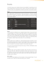
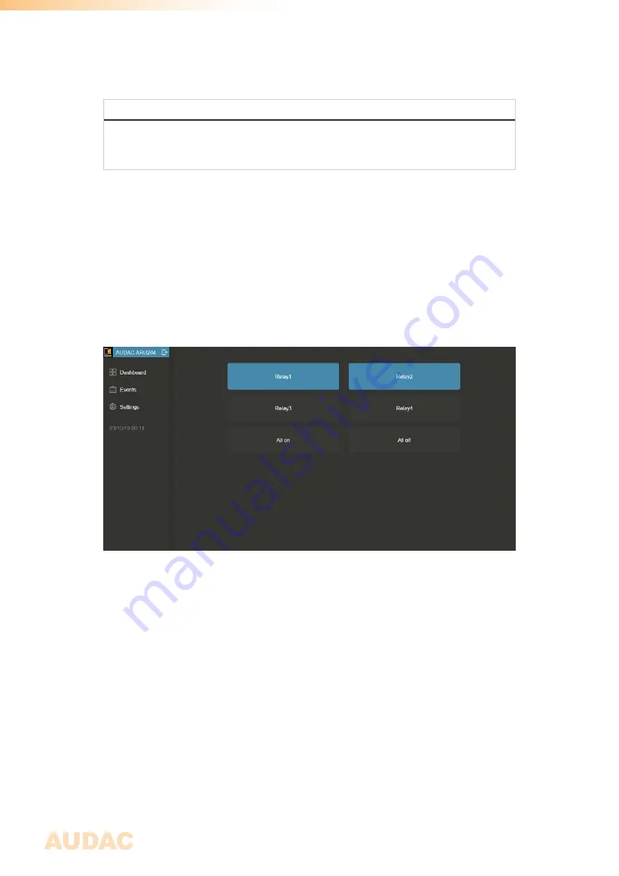
The dashboard (main) screen gives an overview of all the buttons, which are required for
triggering and activating the relays. Depending of the type of relay module, the number of
buttons indicated in this screen will vary (4 or 8 relay activation buttons).
On the bottom of the relay knobs, buttons for selecting all (All on) or deselecting all (All off) are
located, allowing to switch all relays simultaneously. The knobs will be indicated in a neutral
color (grey) when the relays are in the idle state, while they will turn blue when activated.
The text inside the relay knob is default shown as ‘Relayx’ where x represents the number
of the corresponding relay (1 up to 4 for ARU204 or 1 up to 8 for ARU208). This text can be
adjusted according to customers preferences, allowing to create a more clear and intuitive
interface for the user.
The text in the title balk in the top left corner indicates the name which is assigned to the
corresponding ARU20x, which allows customizing, for creating a clear and intuitive overview
when multiple units are being used in one system. The exit icon inside this title balk logs
you off.
Summary of Contents for ARU20 Series
Page 1: ...ARU20x User Manual www audac eu ...
Page 4: ...4 ...
Page 8: ...8 ...
Page 27: ...27 Notes ...
Page 28: ...28 Notes ...


