background image

Product Manual 

ESC1000 – Downlight/LED Smart Connector 


ND 8202-1 11/2015 Users Manual – ESC1000 Emerge Downlight/LED Smart Connector 


Page 2 


www.idealindustries.com 

IDEAL Model ESC1000 LED Smart Connector Installation Instructions 


WARNING: This is a current rated device. Use in applications involving 

Amperage beyond its rating can be dangerous and cause electrical fires. 


Wiring must comply with all applicable electrical codes. 
Turn off power before removing or installing connector. 


TERMINOLOGY 
  
24V Input: Incoming power feed from 24V source (DC Flex-Zone) 
LOAD: Power output from Smart Connector to 24V DC LED Fixture input 
DIM: 0-10 VDC dimming control output from Smart Connector to LED Fixture 
dimming input 
  
CONNECTING THE WIRES 


Power


The 24V Input Connector accepts 12 AWG-18 AWG copper conductors, solid or stranded 
(19 strands or less for 12 AWG-16 AWG, 7 strands or less for 18 AWG). 
Use only one conductor per port and ensure that no copper is exposed on any of the 
wires after installation. 
 

1.


Strip wires to 1/2”. 

2.


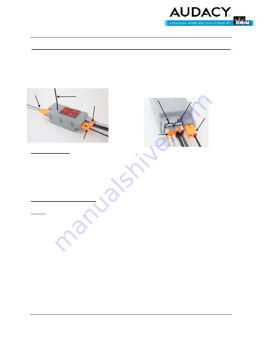
Grip +24V  wire and firmly push conductor into one of the black LINE ports.  See Fig. 2. 

3.


Grip -24V wire and firmly push conductor into one of the unmarked LINE ports.  See Fig. 2. 

4.


For feed-

through (i.e., “daisy-chain”) installations, insert the +24V feed-through conductor 

into the other black line port.  Insert the -24V feed-through conductor into the other 
unmarked LINE port.  See Fig. 2. 

5.


After 24V wire installation, the supply power can safely be disconnected and re-connected 

without re-installing the wires.  To disconnect the supply power, firmly grip the LINE 
connector and pull to separate it from the main body of the Smart Connector.  To re-
connect, simply push the LINE connector into the corresponding port on the Smart 

DIM Connector 

Antenna 

LINE Connector 

LOAD 

Connector 

Fig. 1 

Fig. 2 

LINE  

Connector 

LOAD  

Connector 

LINE neutral & feed-through 

LINE hot & feed-through 

Summary of Contents for ESC1000

Page 1: ...ormation that tells the connector to power on off dim the fixture is acquired via wireless signals that originate from a building automation system or from room controls based on environmental conditions and or predetermined programs KEY FEATURES FCC and IC approved Small form factor Integrated Wire Antenna RoHS compliant PRODUCT CONTENTS The following items are included inside the package Qty Des...

Page 2: ...s for 12 AWG 16 AWG 7 strands or less for 18 AWG Use only one conductor per port and ensure that no copper is exposed on any of the wires after installation 1 Strip wires to 1 2 2 Grip 24V wire and firmly push conductor into one of the black LINE ports See Fig 2 3 Grip 24V wire and firmly push conductor into one of the unmarked LINE ports See Fig 2 4 For feed through i e daisy chain installations ...

Page 3: ... and pull to separate it from the main body of the Smart Connector To re connect simply push the LOAD connector into the corresponding port on the Smart Connector DIM Connector The DIM Connector accepts 18 AWG copper conductors solid or stranded 16 strands or less Use only one conductor per port and ensure that no copper is exposed on any of the wires after installation 1 Strip wires to 3 8 2 Grip...

Page 4: ... After properly installing all wires per the instructions fully extend the antenna See Fig 1 2 Remove the backing of the double sided tape on the ESC1000 exposing the adhesive 3 Insert the antenna through an available open hole in the fixture trough making sure that as much of the antenna extends into the plenum space above the fixture as possible See Fig 4 4 Firmly press the connector into place ...

Page 5: ...PECIFICATIONS Item Description Radio 915 MHz External Antenna Regulatory Approvals FCC Part 15 and Industry Canada Contains FCC ID 2AAMXESC1000 Contains IC 11250A ESC1000 UL916 Transmit Range 300 ft indoors line of sight to an Audacy Gateway or Smart Connector Load Dimming 0 10VDC 10 100 Load Amperage 3 96A Switching Cycles 50 000 Power 24 VDC Operating Temperature 0 C to 70 C Storage Temperature ...

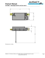
Page 6: ...Product Manual ESC1000 Downlight LED Smart Connector ND 8202 1 11 2015 Users Manual ESC1000 Emerge Downlight LED Smart Connector Page 6 www idealindustries com Dimensions in inches ...

Page 7: ... ESC1000 Emerge Downlight LED Smart Connector Page 7 www idealindustries com SUPPORT Technical support for IDEAL INDUSTRIES products can be initiated through the following methods Website http www idealindustries com support Telephone 1 800 435 0705 Email contactus idealindustries com ...

Page 8: ...receiving antenna Increase the separation between the equipment and receiver Connect the equipment into an outlet on a circuit different from that to which the receiver is connected Consult the dealer or an experienced radio TV technician for help WARNING FCC and IC Radiation Exposure Statement This equipment complies with FCC s and IC s RF radiation exposure limits set forth for an uncontrolled e...

Page 9: ...ks and registered trademarks are the property of their respective owners IDEAL INDUSTRIES INC PRODUCTS INCLUDING HARDWARE AND OR SOFTWARE ARE NOT DESIGNED OR INTENDED TO BE FAIL SAFE FAULT TOLERANT OR FOR USE IN ANY APPLICATION THAT COULD LEAD TO DEATH PERSONAL INJURY OR SEVERE PROPERTY OR ENVIRONMENTAL DAMAGE INDIVIDUALLY AND COLLECTIVELY CRITICAL APPLICATIONS SUCH AS LIFE SUPPORT OR SAFETY DEVIC...

Page 10: ...ance policies at IDEAL Customer may not return products without first obtaining a customer return material authorization RMA number from IDEAL THE WARRANTIES SET FORTH HEREIN ARE EXCLUSIVE AND IN LIEU OF ALL OTHER WARRANTIES REMEDIES AND CONDITIONS WHETHER ORAL OR WRITTEN EXPRESS OR IMPLIED IDEAL DISCLAIMS ALL OTHER WARRANTIES WHETHER EXPRESS IMPLIED OR STATUTORY INCLUDING WITHOUT LIMITATION ANY W...

Reviews: