24
25
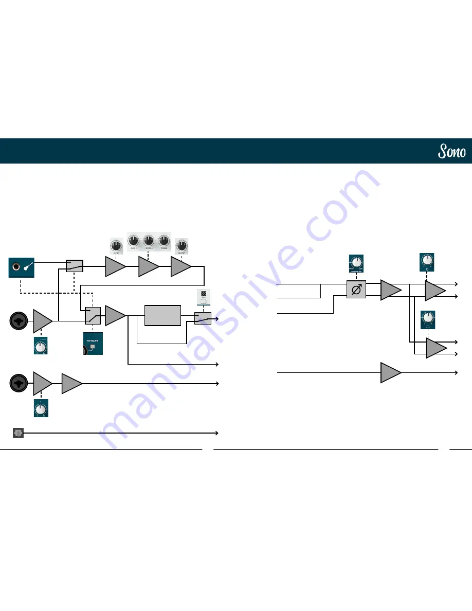
Signal Flow Diagrams
Inputs 1+2
Speakers
Headphones
To-Amp
Digital Inputs
DAW Playback
1+2
DAW Playback
3
Signal Flow Diagrams
Neutrik
Neutrik
Mic1/
DI
No
CAB
Mic 2
Digi
1-8
+60dB
+60dB
Input
Sensing
Switching
Guitar
Input
Mic 1
Mic 2
Optical
Input
Sono Output Flow Diagram
There are two ways in which the Sono outputs
can be controlled, either using the Monitor Mix
Control on Sono itself, or using the Sono Mixer.
Both modes of operation can be seen below.
More information about the mixer can be
found later in this manual.
Sono Output using Monitor Mix
The To-Amp output on Sono automatically
senses when a jack is connected and will re-
route DAC output 3 to the To-Amp output and
the headphones output will instead be fed
from DAC 1+2 instead.
Sono Input Flow Diagram
The below diagram shows how the input
signal is routed through Sono.
The Guitar input will automatically sense
when a jack is connected and when a jack is
present. The Mic 1 input will be switched out
and the ‘To Valve’ button overridden.
When the C.A.B button is illuminated, the
Torpedo Processing is active. Pressing and
holding the C.A.B button will bypass the
processing and the switch will become unlit.
DAC
1+2
DAC
3
Volume
Volume
Input
EQ
Output
ADC
ADC
Torpedo Cabinet
Processing


