3
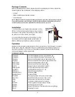
Package Contents
Before installing this product, please check the packaging to make certain the
following items are contained in the shipping carton:
• 970A-1
• DB9 to DB9 serial interface cable
• User Manual
Installation
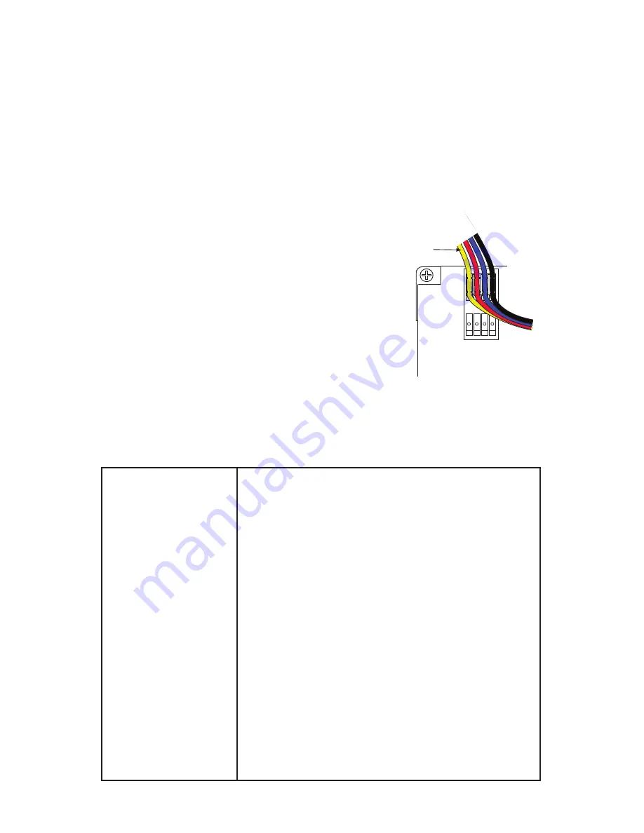
1. Connect the 4-pin System Bus header on the
970A-1 to the Access system bus at any unused
connector. The system bus wiring is color coded
as yellow, red, blue, black (
see right
).
2. Connect the Serial port on the 970A-1 to the
host device with an appropriate serial cable. A
DB9 to DB9 serial interface cable is included.
Operation
Default communication parameters for the host port are 19,200 baud, no parity,
8 bits and 1 stop bit. Operation may be verified using a terminal program on
the host computer. If you have any questions please contact Audio Authority
Technical Support at 800-322-8346.
Command Listing
+Sgg:pp
+Egg:pp
-Sgg:pp
-Egg:pp
DISC Sgg
DISC Egg
MUTE
END MUTE
SLIMIT n
DISCALL
DISABLE ALL
ENABLE ALL
STATUS
VOL nnn
VDN
VUP
SLEEP
WAKE
RESET
HELP
Connect Speaker group ‘gg’ product ‘pp’
Connect Electronic group ‘gg’ product ‘pp’
Disconnect Speaker group ‘gg’ product ‘pp’
Disconnect Electronic group ‘gg’ product ‘pp’
Disconnect Speaker group ‘gg’
Disconnect Electronic group ‘gg’
Begin muted multi product switch
End muted multi product switch
Set Speaker Limit to n (1..4)
Disconnect everything
Disable PSBs
Enable PSBs
Request system info and current state
Set 988 volume to level ‘n’ [0...127]
Decrease volume level by 4 steps
Increase volume level by 4 steps
Place system in power down mode
Exit power down mode
Reset 970 (Note: This disconnects everything)
Display this text
SYSTEM
BUS
YELLOW WIRE
ALWAYS ON
THIS SIDE OF
PLUG
GROUP
MODULE ID
BLACK
BLUE
RED
YELLOW
Note: Please retain the original packing material in case the unit must be returned.
If you find any items are missing, contact Audio Authority immediately. Have the
model number and invoice available for reference when you call.
Summary of Contents for 970A-1
Page 1: ...User Manual Model 970A 1...

