SF-16B Digital Amplifier Installation and Operation Guide 7
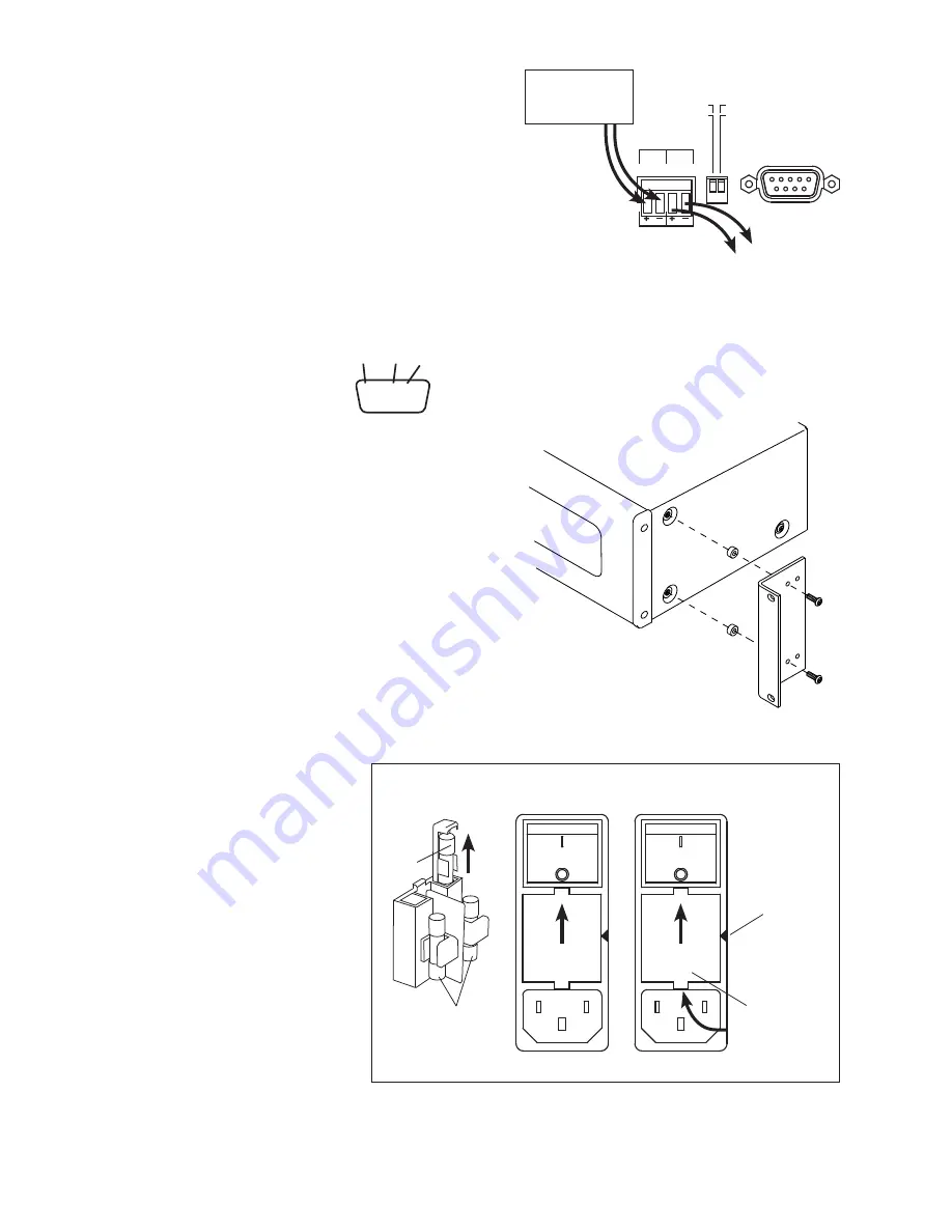
Changing the Power Fuse
Before changing the fuse, find and correct
the excessive impedance load or wiring
short that caused the fuse failure.
The fuse compartment contains two extra
fuses that can be used to replace blown
fuses in the field. Access the replacement
fuses by sliding out a compartment behind
each fuse, as shown in Figure 9.
• Remove the power cord.
• Carefully remove the fuse cover using a
flat blade screwdriver.
• Inspect both fuses to determine which
one is blown.
• Replace the blown fuse with a spare fuse,
or a fuse of the same value.
• Orient the fuse cover so that the arrow
points toward the correct voltage for your
region as shown in Figure 9.
CAREFULLY PRY
WITH A SMALL
SCREWDRIVER
FUSE COVER
ARROW
INDICATES
VOLTAGE
200-240 Volts
(5A Fuses)
100-120 Volts
(10A Fuses)
SPARE
FUSE
ACTIVE
FUSES
Figure 9
Figure 8
Figure 7
SF-16B CONNECTIONS - System Trigger
(5V-24V AC/DC)
The System Trigger input on the SF-16B allows equipment such
as AV receivers or power managment devices to put the SF-16B in
standby when not in use, thereby greatly conserving energy usage.
To enable the System Trigger:
1. Make system trigger connections as illustrated in Figure 13.
2. Power the SF-16B, then apply power to the triggering device.
3. Set System Trigger DIP switch in the up (TRIGGER MODE)
position.
1/2
1 2
3
4
5
6
7
8
9
10
11 12
13
14
15 16
SPEAKER OUTPUTS (CLASS 2 WIRING)
SERIAL
TRIGGER MODE
ALWAYS ON
BUS INPUT
1:1 INPUTS
701-13306
DB25 AUDIO INPUT
AUDIO LOOP OUTPUT
100-120V~ 50-60 Hz 1125W
Replace Fuses Only
with T 10A, 250V
Remplacer Uniquement avec
Fusible T 10A, 250V
Set voltage selector
and install correct
fuses according to
local power supply.
Régler le sélecteur
de tension et
installer les fusibles
corrects selon
l’alimentation locale.
4002715
ETL LISTED CONFORMS
TO UL STD 60065
CERTIFIED TO CAN/CSA
STD C22.2 NO. 60065
Audio Authority® Corp. • 2048 Mercer Rd. Lexington, KY 40511 USA
800-322-8346 • 859-233-4599 • www.audioauthority.com
Model SF-16 8-Zone Digital Amplifier
VOLTAGE SELECTOR
BUS
GAIN
L
R
A
B
C
D
E
F
G
H
PDF User Manual
IN OUT
SYSTEM
TRIGGER
5V - 24V AC / DC
1/3
PDF User Manual
TO NEXT SF-16B
SYSTEM TRIGGER
INPUT
Figure 6
POWER
MANAGEMENT
DEVICE
Serial Connection
Firmware updates are accomplished
via the serial port and a Windows
PC firmware update utility. Serial
connection pins are shown in Figure 7.
SF-16B Rack Mounting
The SF-16B is designed so that it may be installed either on a shelf
or in a standard 19-inch equipment rack. If rack mounting, remove
the feet and the cover screws adjacent to the front panel of the unit.
Reuse the cover screws to mount the rack adapters supplied with
the SF-16B. Be sure to place a spacer under the adapters at every
screw location. Secure the SF-16B to the rails of the equipment
rack with the screws supplied, and use appropriate chassis
supports, such as Middle Atlantic CSA Series.
1/2
1 2
3
4
5
6
7
8
9
10
11 12
13
14
15 16
SPEAKER OUTPUTS (CLASS 2 WIRING)
SERIAL
TRIGGER MODE
ALWAYS ON
BUS INPUT
1:1 INPUTS
701-13306
DB25 AUDIO INPUT
AUDIO LOOP OUTPUT
100-120V~ 50-60 Hz 1125W
Replace Fuses Only
with T 10A, 250V
Remplacer Uniquement avec
Fusible T 10A, 250V
Set voltage selector
and install correct
fuses according to
local power supply.
Régler le sélecteur
de tension et
installer les fusibles
corrects selon
l’alimentation locale.
4002715
ETL LISTED CONFORMS
TO UL STD 60065
CERTIFIED TO CAN/CSA
STD C22.2 NO. 60065
Audio Authority® Corp. • 2048 Mercer Rd. Lexington, KY 40511 USA
800-322-8346 • 859-233-4599 • www.audioauthority.com
Model SF-16 8-Zone Digital Amplifier
VOLTAGE SELECTOR
BUS
GAIN
L
R
A
B
C
D
E
F
G
H
PDF User Manual
IN OUT
SYSTEM
TRIGGER
5V - 24V AC / DC
1/3
PDF User Manual
UP
1/2
1 2
3
4
5
6
7
8
9
10
11 12
13
14
15 16
SPEAKER OUTPUTS (CLASS 2 WIRING)
SERIAL
TRIGGER MODE
ALWAYS ON
BUS INPUT
1:1 INPUTS
701-13306
DB25 AUDIO INPUT
AUDIO LOOP OUTPUT
100-120V~ 50-60 Hz 1125W
Replace Fuses Only
with T 10A, 250V
Remplacer Uniquement avec
Fusible T 10A, 250V
Set voltage selector
and install correct
fuses according to
local power supply.
Régler le sélecteur
de tension et
installer les fusibles
corrects selon
l’alimentation locale.
4002715
ETL LISTED CONFORMS
TO UL STD 60065
CERTIFIED TO CAN/CSA
STD C22.2 NO. 60065
Audio Authority® Corp. • 2048 Mercer Rd. Lexington, KY 40511 USA
800-322-8346 • 859-233-4599 • www.audioauthority.com
Model SF-16 8-Zone Digital Amplifier
VOLTAGE SELECTOR
BUS
GAIN
L
R
A
B
C
D
E
F
G
H
PDF User Manual
IN OUT
SYSTEM
TRIGGER
5V - 24V AC / DC
1/3
PDF User Manual
200V - 240V
100V - 120V
UP
5 4 3 2 1
9 8 7 6
GND RX TX
200V - 240V
100V - 120V


