


SDS-1001-101-x Installation Manual
Document #540306, Rev IR, 04/2005
Page 10 of 12
4.0 Troubleshooting
4.1
General Troubleshooting Procedures
•
Verify power to the unit by confirming that +28 VDC power is applied to
the proper pins on the unit. Use a voltmeter to verify correct level.
•
Remove power from the unit for at least one (1) minute and then
reapply power.
•
Recheck all connections to the unit for security. Check all harness
runs for possible pinching. Recheck all pin outs for application
accuracy.
4.2 Instructions for Continued Airworthiness
No periodic scheduled maintenance or calibration is required for continued
airworthiness of the SDS-1001-101-x. If the unit fails to perform to
specifications, it must be removed and serviced by a qualified service
facility.
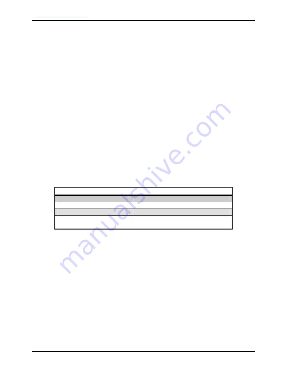
5.0 Specifications
Physical Specifications
Housing Aluminum
Weight
Approx. 0.69 lb / 0.31 kg
Dimensions
(l x w x h)
4.20" x 5.61" x 1.18"
10.67 cm x 14.25 cm x 3.0 cm


