VCP-010-06(-07)-x Installation & Operation Manual
Document # 540236, Rev IR, 11/2002
Page 12 of 21
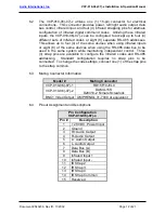
6.2 The VCP-010-06(-07)-x utilizes one (1) 15-pin connector for electrical
connections. This connector provides power, left/right audio output, data
bus control, infrared input, and four (4) infrared strapping pins for alternate
configuration of infrared digital command codes. Utilizing these infrared
inputs, the VCP-010-06(-07)-x can be configured to accept up to four (4)
different sets of infrared codes or eight (8) separate RS-485 addresses.
This allows up to four (4) of the same devices when using infrared inputs
or eight (8) of the same devices when using the RS-485 data bus to be
used in the same system while maintaining independent control. Three
(3) strap pins are available to configure the infrared codes and RS-485
addressing. Standard configuration requires no strap pins to be
connected. To change the code settings, connect one (1) of the strap pins
to the strap common.
6.3 Mating Connector Information
Model #
Mating Connector
VCP-010-06(-07)-1 RD15F10JVL0
VCP-010-06(-07)-2
DAMA-15S
D20418-2 Female Screwlock
BNC1 Video Output AMPHENOL 31-7008 or equivalent
6.4 Pinout Assignment and Descriptions
Pin Configuration
VCP-010-06(-07)-x
Pin #
Description
1
+ 28 VDC, Power Input
2 Ground
3
R+ Audio Output
4
R- Audio Output
5
L+ Audio Output
6
L- Audio Output
7
Data Bus (A)
8
Data Bus (B)
9
Infrared Input +
10
Infrared Input -
11 IR
Strap
2
12 IR
Strap
3
13 IR
Strap
4
14
IR Strap Common
15 Reserved


