VCP-015-02-x Installation & Operation Manual
Document # 540228, Rev A, 05/2003
Page 8 of 18
3.10
DO NOT
leave cassette tapes loaded in the unit with no power applied.
3.11
NO
scheduled
maintenance is required to ensure airworthiness.
3.12
DO NOT
insert any screw more than 0.25 inch into the case. Mounting
holes on the unit provide multiple anchoring points. These threaded
inserts do not have physical stops. Care should be taken not to penetrate
the outer casing with any screw by more than 0.25 inch. This could result
in serious damage to the video cassette player.
3.13
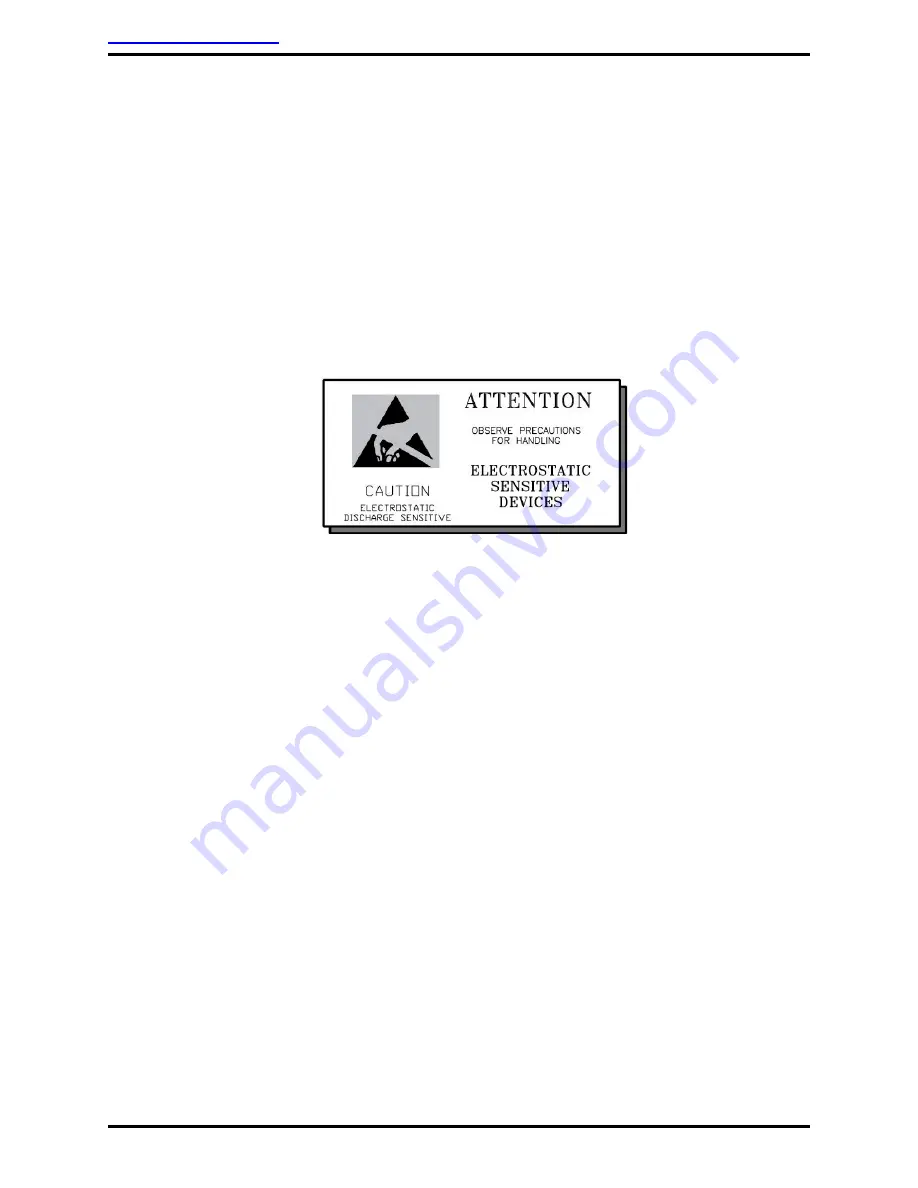
ESD
(Electro Static Discharge) guidelines shall be followed.
4.0 Wiring
Requirements
4.1 Introduction
The installing agency shall supply and fabricate all external cables. The
length and routing of external cables should be carefully studied and
planned before attempting installation of the equipment. Allow adequate
space for installation of cable and connectors. Avoid sharp bends and
placing cables near aircraft control cables. Maintain a minimum clearance
of three (3) inches from any control cable. If wiring is run parallel to
combustible fluid or oxygen lines, maintain a separation of six (6) inches
between the lines.
4.2 Power Wires
All power and ground wires require 22 AWG, MINIMUM
,
shielded twisted
pair with the shield properly bonded at one (1) end only. Power ground
wires shall be bonded to electrically conductive chassis mounting point
with <1
Ω
resistance using <50
Ω
impedance cable. Twisted shielded pair
cable shall be in accordance with
NEMA WC 27500
or equivalent.


