background image

4

B. Select Open Frequency Scan Function

1. From the normal operating mode, press and hold the set 

button until display flashes.

2. To select scan function, press and hold CH SELECT/SCAN

button, continue to hold until available frequency is 

automatically displayed. 

3. (a) To select frequency, press and hold SET button until 

display stops flashing.

(b) To cancel frequency selection, simply press the SET 

button 

once. 

The receiver then returns to the normal 

operation without making any changes

.

Figure D

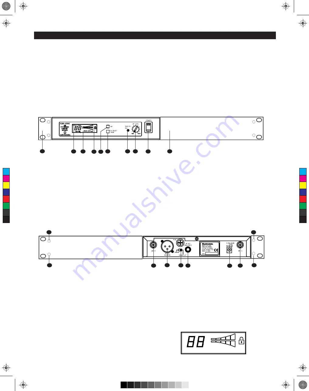
Front Panel Controls and Functions (Figure. B)

1. POWER SWITCH/INDICATOR: Press switch on, and the  

"Power" indicator will light.

2. LCD WINDOW: Liquid Crystal Display indicates control 

settings and operational readings. See Figure D for 

examples.

3. TUNER OPERATION INDICATOR: Indicates which Tuner 

(A or B) has the better reception and is in operation. 

4. SET BUTTON: Activates access to Frequency/Scan 

mode and sets or cancels selected function when used in 

combination with CH SELECT/SCAN button (Item 5).5.

5. CH SELECT/SCAN BUTTON: Use in conjunction

with the SET button (Item 4) to select operation frequency 

and scan function.

Figure B

Receiver Controls and Functions

6. AF LEVEL CONTROL: Adjusts audio output level of both AF 

Output jacks; maximum output is fully clockwise.

7. SQUELCH CONTROL: Adjusts level of noise-muting circuit

(preset at factory but can be adjusted as circumstances

warrant).

8. MOUNTING ADAPTERS: For mounting the receiver in any 

standard 19" rack. Attach adapters to the receiver with the 

screws supplied and remove the four receiver feet. (Use 

optional AT8616 joining-plate kit to mount two ATW-R160 

receivers side-by-side.)

9. PLL Lock indicator: This indicates Phased Lock Loop 

frequency controlled oscillator has locked displayed 

frequency.

Rear Panel Controls and Functions (Figure C)

10. ANTENNA INPUT JACK: BNC-type antenna connector for 

Tuner “B.” Attach the antenna directly, or extend it with a 

low-loss antenna cable. See the “Antennas” section on 

page 3 for more details.

11. ANTENNA INPUT JACK: Input for Tuner “A.” Attach the 

antenna directly, or extend it with a low-loss antenna cable.

12. GROUND LIFT SWITCH: Disconnects the ground pin of the 

balanced output jack (12) from ground. Normally, the switch 

should be to the left (ground connected). If hum caused by 

a ground loop occurs, slide switch to the right (ground 

lifted).

13. BALANCED AUDIO OUTPUT JACK: XLRM-type connector. 

A standard 2-conductor shielded cable can be used to 

connect the receiver output to a balanced microphone-level 

input on a mixer or integrated amplifier.

14. UNBALANCED AUDIO OUTPUT JACK: 

1

/

4

" phone jack. Can 

be connected to an unbalanced aux-level input of a mixer, 

guitar amp or tape recorder.

15. POWER INPUT JACK: Connect the DC plug from the 

included AC adapter.

16. ATW-RA1 Rack-Mount Antenna kit mounting Holes: Mount

optional front-mount antenna kit ATW-RA1 on these holes.

Power On/Off

To turn the receiver on, press the Power switch. The Power

light and the LCD window will come on after about 1-2

seconds.  The operating channel number and frequency will be

displayed in the window after the power-up sequence. To turn

the receiver off, press the Power switch again.

How to Make Setting Changes

A. Select Frequency Manually

1. From the normal operating mode, press and hold the set 

button until display flashes.

2. To select frequency, press CH SELECT/SCAN button once 

at a time until desired channel is displayed (1 to 9, A to F).

3. (a) To select frequency, press and hold SET button until 

display stops flashing.

(b) To cancel frequency selection, simply press the SET 

button 

once. 

The receiver then returns to the normal 

operation.

CHANNEL

840.125

MHZ

AF
RF

ANT   A

ANT   B

2

1

3

4 5

6

7

8

8

10

11

13

12 14

15

9

16

16

16

Figure c

16

C

M

J

CM

MJ

CJ

CMJ

N

4.pdf   26/11/08   17:02:41

Summary of Contents for ATW-1662

Page 1: ...l UHF Wireless Systems ATW 1661 UniPak Transmitter System ATW 1662 Handheld Dynamic Microphone System ATW 1663 Handheld Condenser Microphone System Installation and Operation 0700 C M J CM MJ CJ CMJ N 1 pdf 26 11 08 17 01 03 ...

Page 2: ... in the ATW R160 receiver opens only when a 1600 Series transmitter is detected reducing the possi bility of interference As a result 1600 Series transmitters and receivers must be used together and should not be used with components from other Audio Technica wireless systems or with those of other manufacturers Please note that in multiple system applications there must be a transmitter receiver ...

Page 3: ...he back panel to the mixer The two isolated audio outputs permit simultaneous feeds to both unbalanced and balanced inputs For example both a guitar amp and a mixer can be driven by the receiver Antennas Attach the included pair of UHF antennas to the antenna input jacks The antennas are normally positioned in the shape of a V both 45 from vertical for best reception Antennas can be remotely locat...

Page 4: ...d Functions Figure C 10 ANTENNA INPUT JACK BNC type antenna connector for Tuner B Attach the antenna directly or extend it with a low loss antenna cable See the Antennas section on page 3 for more details 11 ANTENNA INPUT JACK Input for Tuner A Attach the antenna directly or extend it with a low loss antenna cable 12 GROUND LIFT SWITCH Disconnects the ground pin of the balanced output jack 12 from...

Page 5: ...n for the maximum battery life Hi High position can be selected for maximum range Note range decreases when the switch is set at Lo position Special Note If accessing de regulated frequencies between 863 to 865MHz Ch C to F ATW T161 must be set to RF Low J e r u g i F I e r u g i F UniPak Transmitter Input Connection Connect an audio input device microphone or guitar cable to the audio input conne...

Page 6: ...system that pro vides enhanced rejection of RF interference The squelch control on the front panel of the receiver is preset at the factory but can be adjusted if you are using the system in a high RF inter ference area This adjustment can cause a reduction in the use able range of the wireless transmitter so set the control to the lowest position which reliably mutes the unwanted RF signals Input...

Page 7: ...t has the fewest possible obstructions between it and the normal location of the transmitter Line of sight is best 3 The transmitter and the receiver should be as close together as conveniently possible but no closer than three feet 1 m 4 Avoid placing the receiver in a low or shielded location where the transmitter and receiver antennas are not visible to each other If necessary use remotely loca...

Page 8: ... mount adapters ATW T161 UNIPAK TRANSMITTER RF Power Output According to National Regulations Spurious Emissions ETS 300 422 2 Dynamic Range 110 dB A weighted Input Connections High impedance low impedance bias Batteries not included Two 1 5V AA alkaline Current Consumption 160 mA typical s r u o h 8 h g i H s r u o h 6 y l e t a m i x o r p p A e f i L y r e t t a B Low depending on battery type ...

Page 9: ...nds etc For use with ATW R160 receivers Takes RF cables with BNC connectors not included see RF Cables below ATW A49 Pair of UHF wide band directional LPDA log periodic dipole array antennas provide enhanced signal pickup for UHF wireless systems throughout a wide band range 440 900 MHz Each antenna paddle is matched to 50 ohms impedance with and integral hi quality low loss BNC connector 6dB gain...

Page 10: ...hts Distorted sound RF and or AF level meters may show good signals The transmitter audio level is too high See p 6 7 Received RF level may be too low only one or two bars Batteries may be weak check BATT condition indicator See p 5 Troubleshooting Guide Momentary loss of sound noisy sound as transmitter is moved around performing area Transmitter and receiver antennas not in line of sight or perh...

Page 11: ...note that Band UK antenna colour code is grey Cannel No 0 1 2 3 4 5 6 7 8 9 A B C D E F Frequency MHZ 840 125 840 375 841 125 841 375 844 250 845 500 854 900 855 275 856 575 857 625 860 900 861 200 863 125 863 375 864 125 864 375 1 O O O O O O O O O O O O O 2 O O O O Band Co ordinate Shared De regulated Group 11 C M J CM MJ CJ CMJ N 11 pdf 26 11 08 17 09 43 ...

Page 12: ... How to Choose band A or B as open frequency scan group prior to selecting Open frequency Scan function use manual frequency selection method and set a start frequency from band A Group A scan or start frequency from band B group B Scan Please note that Band EU antenna colour code is black Cannel No 0 1 2 3 4 5 6 7 8 9 A B C D E F Frequency MHZ 795 500 796 000 797 900 800 975 802 025 807 500 809 5...

Page 13: ...ica att denna ATW T161 ATW T162 står I överensstämmelse med de väsentliga egenskapskrav och övriga relevanta bestämmelser som framgår av direktiv 1999 5 EG Undertegnede Audio Technica erklærer herved at følgende udstyr ATW T161 ATW T162 overholder de væsentlige krav og øvrige relevante krav i direktiv 1999 5 EF Hiermit erklärt Audio Technica dass sich dieser diese dieses ATW T161 ATW T162 in Übere...

Page 14: ...nts of the relevant standards as listed herewith Product UHF Wireless Microphone System Model Type Number ATW R160 Receiver ATW T161 Beltpack Transmitter ATW T162 Handheld Transmitter ATW T163 Handheld Transmitter Directive and Standard Used Radio EN 300422 1 V1 2 2 2000 08 EN 300422 2 V1 1 1 2000 08 EMC EN 301489 1 V1 6 1 2005 09 EN 301489 9 V1 4 1 2007 11 LVD EN 60065 2002 A1 2006 Year of Affixi...

Page 15: ... purchased in the EU are warranted for one year from date of purchase by Audio Technica Limited to be free of defects in materials and workmanship In event of such defect product will be repaired promptly without charge or at our option replaced with a new product of equal or superior value if delivered to Audio Technica Limited prepaid together with the proof of purchase Prior approval from Audio...

Page 16: ...io technica co uk Audio Technica Europe A Division of Audio Technica Ltd Email sales audio technica europe com Web www audio technica europe com Technica House Royal London Industrial Estate Old Lane Leeds LS11 8AG UK Tel 44 0 113 277 1441 Fax 44 0 113 270 4836 C M J CM MJ CJ CMJ N last pdf 26 11 08 17 03 04 ...

Reviews: