5
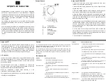
M2 Transmitter Controls
(front panel)
(rear panel)
1.
Power LED.
Lights red when power is applied.
2.
Power switch.
Depress once to turn on. Depress again to turn off.
3.
L/1 and R/2 trim control.
Controls level of corresponding audio input.
4.
Input level indicator.
Shows signal level from audio input L/1
and R/2.
5.
Frequency group selector.
Selects frequency group.
6.
Frequency channel selector.
Selects frequency channel.
7.
Flexible antenna.
Permanently attached antenna transmits to
receivers.
8.
Data port.
For factory use only.
9.
Loop output.
The R/2 XLR jack duplicates the unprocessed signal
of the R/2 input; the L/1 XLR jack duplicates the unprocessed signal
of the L/1 input. Not affected by front panel settings.
10. Attenuators.
Offer -20 dB, -10 dB, and 0 dB attenuation for each
input.
11. Inputs.
Combination input jacks offer both XLR and
1
/
4
" jacks.
12. DC input.
Plug the included power supply in here.
13. Cord hook.
Loop the small DC cord around the cord hook to keep
the DC plug from pulling out accidentally.
Phantom Power
The transmitter does not provide phantom power, but
it does allow
phantom power to pass through from your phantom power supply
to a device plugged into either input jack.
CAUTION: If connecting instruments to a mixing console through
the transmitter loop output, then use a direct box to prevent
damage to your instruments and/or equipment from the mixing
console’s phantom power; i.e. hook your instrument into a direct
box, then hook your direct box into the transmitter.
EN
2
3
4
10
11
13
9
7
1
8
12
5
6
3
9
10
11
P52001_M2-System_OM 2/13/08 4:16 PM Page 5


