- 6 -
A10-RACK User Guide
Powering
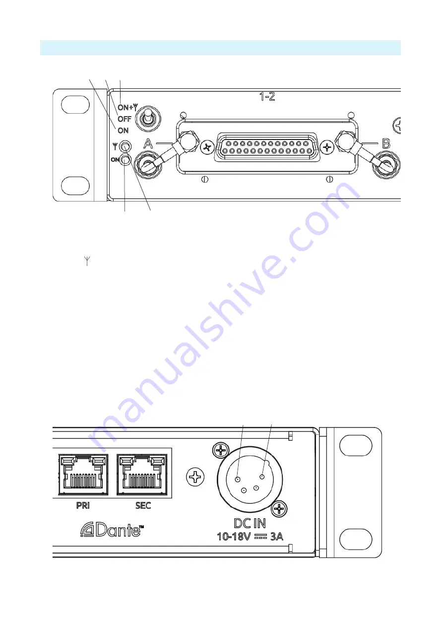
The Power switch on the front panel is a three-way switch.
2
1
3
5
4
Figure 4: Closeup of Leftmost Slot on Front Panel of A10-RACK
1 -ON +
A10-Rack power on with 12V power at the
A and B antenna connectors.
2 -OFF
A10-Rack power off.
3 -ON
A10-Rack power on with no bias power at
the A/B antenna connectors.
4 -Antenna Power Indicator
LED illuminates yellow when bias power is
being provided to A and B antennas.
ª
If yellow LED does not illuminate when switch is in
PWR+ANT position, a short-circuit fault condition is
present on either A or B antenna inputs.
5 -Power Indicator
LED illuminates green when A10-Rack is
powered on.
The A10-RACK is powered with a standard 4-pin F-XLR 10-18vdc power supply (sold
separately), such as the Sound Devices XL-WP4. Power to A10-RACK needs to be capable of
providing 3A minimum for proper powering of the A10-RACK and the slot receivers.
Ground (Pin 1)
Power (Pin 4)
Figure 5: Closeup of Rightmost end of Back Panel of A10-RACK


