background image

Summary of Contents for PX-603

Page 1: ...AUDIOACCESS PX 603 MULTI ROOM EXPANDER PRELIMINARY SERVICE MANUAL Harman Consumer Group 250 Crossways Park Dr Woodbury New York 11797 ...

Page 2: ......

Page 3: ......

Page 4: ......

Page 5: ......

Page 6: ......

Page 7: ......

Page 8: ......

Page 9: ......

Page 10: ......

Page 11: ......

Page 12: ......

Page 13: ......

Page 14: ......

Page 15: ......

Page 16: ......

Page 17: ......

Page 18: ......

Page 19: ......

Page 20: ......

Page 21: ......

Page 22: ......

Page 23: ......

Page 24: ......

Page 25: ......

Page 26: ......

Page 27: ......

Page 28: ......

Page 29: ......

Page 30: ......

Page 31: ...Madrigal Audio Laboratories P O Box 781 Middletown CT 06457 0781 860 346 0896 FAX 860 347 6251 XXXXXXX TROUBLESHOOTING GUIDE MARCH 9 2000 ...

Page 32: ...locked up lights come on but no functions System locked up Zone or system locks up after ON button is pressed Intermittent keypad lock up or control Unplug isolate all keypad wires from control unit and test unit functions from front panel Test each keypad on system individually Test using an alternate KPS addressed for the same zone For alternate front panel control of zones use the ROOM button f...

Page 33: ...t audio does not follow change Check DIP Switch settings Check data bus wiring Use correct settings for system and zone Correctly connect wiring IR input on keypad does not respond to commands issued from hand held IR remote Check position of DIP Switch 9 Does the remote have good batteries To enable IR put DIP switch 9 in the down position Replace batteries in remote KP3 keypad does not function ...

Page 34: ...th same value Audio always very loud in all zones Sources can be controlled but volume can not Check PX 600 back panel outputs Variable audio comes out of the preamp section and NOT the zone outputs Use preamp output not zone outputs Audio drops out then returns What volume level does this occur Does this happen when music has soft passages in it Does it always happen at the same volume level Is i...

Page 35: ...ion System or zone turns on by itself Is there an extra ordinary amount of light shining on any keypad or the front panel of the system Check for stuck button on keypad If using an outboard control system check parameters of control system Does it have functions for timed operations Disable IR receiver in KPS keypad by putting DIP switch 9 in the UP position If it is coming in through the front pa...

Page 36: ...o shorted wires or broken connectors Characters remain on LCD after back light goes off After PX connect or MRX connect this is normal If this happens at any other time call Customer Support Tuner frequency displayed on LCD MRX does not match station being listed to Check that tuner set up is set for US standards US frequencies should be set at 2MHz Use the tuner preset button 1 and MUTE to activa...

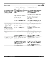
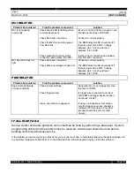
Page 37: ...er a 100Ohm watt 5 resistor to shunt the voltage MRX fan always runs Check thermo couple on amplifier heat sink If always closed then replace MRX fan never runs Check thermo couple on amplifier heat sink Check fan windings If always open when hot replace Use an ohmmeter to check for continuity If open replace fan PX 603 RELATED Problem Encountered Find the problem component solution PX 603 room do...

Page 38: ...to PX 603 input Set switches to correct system zone and room address on PX 603 and KPS if used Insure correct connection and polarity to data bus When using KP3 keypads a 6 conductor wire must be home run PX 603 LED indicator light always stays Green Unit is always ON Check DIP switch settings Check Data bus connection Check ALL ON group settings Was the room turned on by issuing an All On command...

Page 39: ...ources with the system Some receivers short the input to ground when in the stand by condition Disconnect cable If the problem goes away then use a ground loop isolator in line with the cable input feed Disconnect wiring feeding the local system If problem goes away use an in line RCA style ground loop isolator to bring the signal to the local system MULTI SYSTEM RELATED Problem Encountered Find t...

Page 40: ...t the MCI Voltage between pins 1 4 should read between 8 to 13VDC PDM RELATED Problem Encountered Find the problem component solution Page Doorbell Module chimes constantly Check jumper settings Check trigger wiring Insure door station is powered Set jumpers for correct triggering See top cover of PDM Is trigger wire connected correctly at both PDM and trigger device location Continuity shorts If ...

Page 41: ......

Page 42: ......

Page 43: ......

Page 44: ......

Page 45: ......

Page 46: ......

Page 47: ......

Page 48: ......

Page 49: ......

Page 50: ......

Page 51: ... CAP RIGHT 610 2712 001 EPROM BLANK 27C512 610 1101 000 EPROM VERSION 1 1 PROGRAMMED 640 3000 150 FILTER CAP 15000uF 35V 720 2500 010 FOOT SNAP IN GOLD 760 4603 003 B FRONT PANEL PX 603 664 2204 000 FUSE 5X20mm 4A SB 664 2220 150 FUSE PICO 15A 680 2000 000 HEATSINK TO 220 605 2202 138 IC 74HC138 DECODER 605 2213 541 IC 74HC541 OCTAL BUFFER TRI STATE 605 2213 573 IC 74HC573N LATCH TRI STATE 605 221...

Page 52: ...000 RES METAL WIRE 0 OHM 1 8W 654 0030 100 RES MF 10 0K OHM 1 8W 1 654 0030 110 RES MF 11 0K OHM 1 8W 1 654 0020 249 RES MF 2 49K OHM 1 8W 1 654 0020 240 RES MF 2 4K OHM 1 8W 1 654 0010 200 RES MF 200 OHM 1 8W 1 654 0020 324 RES MF 3 24K OHM 1 8W 1 654 0010 681 RES MF 681 OHM 1 8W 1 654 0020 910 RES MF 9 1K OHM 1 8W 1 654 0020 124 RES MF 1 24K OHM 1 8W 1 656 2237 100 RES SIP 9 10K 650 1000 001 RES...

Page 53: ...TS LIST 800 3160 000 00 600 612 603 BOX 805 3000 007 600 612 603 FOAM SET 610 1101 000 ICS DIG PROG EPROM PX 603 V1 01 610 1102 000 ICS DIG PROG EPROM PX 603 V1 02 PX 603SW1 02 AA PX 603 V1 02SW FIELD UPDATE KIT ...

Page 54: ...ioaccess Technical Support Please have part number and serial number available when ordering Software v1 02 Part PX 603SW1 02 Audioaccess Technical Services 888 691 4171 Condition Updates Condition PX 603 rooms function erratically after receiving status request command Example Sources taking a long time to switch Sources do not switch Volume control inoperative Volume control slow to respond Solu...

Page 55: ... RS 232 devices n PX 603 ROOM STATUS REQUEST hex value 63 Device type 06 n MAIN ROOM STATUS REQUEST hex value 63 Device type 04 PX 700 Commands The following commands sent by the PX 700 would cause the erratic behavior when a PX 603 is connected to a PX 700 while programming the PX 700 n Downloading the installation into a PX 700 n Learning IR into the installation manager IR library n Playing IR ...

Page 56: ...he cable must have the connector cut off and then re terminated in a one to one connection To determine if your wiring is correct look at both connectors together The visible color code should be identical from left to right Installing the Connectors Terminate wire ends with RJ11 six pin six conductor modular plugs Standard six conductor wire is color coded in orange green blue green with white wh...

Page 57: ... this condition affects the PX 603 it is affected by software within other units The table below shows the software from these units that will experience the turn on volume not being set PX 603 any PX 700 v1 1 Installation Manager v1 1 0 5 NOTE A new version of the Installation Manager v2 0 1 2 allows for the turn on volume of a PX 603 expansion room to be set from the Installation Manager Once yo...

Page 58: ...EM ZONE and ROOM to the room use wish to set the volume in e Select Device Type 06 Px603 and Command F1 Mute NOTE If the command is not available close the Installation Manger and repeat step 1 f Leave the SEND MESSGAE window open and go to STEP 3 Set Expansion Room Level STEP 3 Set Expansion Room Level a Go to the Keypad that is addressed to the PX 603 expansion room you wish to set b Turn the Ro...

Page 59: ...PX 603 EPROM Replacement ...

Page 60: ...Table of Contents PX 603 EPROM Replacement Table of Contents OVERVIEW 1 CAUTIONS BEFORE BEGINNING 1 TOOLS REQUIRED 1 REPLACING THE EPROM 1 EPROM LOCATION 2 CONTACTING TECH SUPPORT 3 ...

Page 61: ... equipment from the unit 3 Remove the top cover using a 2 Phillips screwdriver 4 Locate the EPROM at location U711 on the Main PCB The EPROM is located in a socket in front of the keypad dipswitches and to the left of the microprocessor See Diagram 1 for reference 5 Note the direction of the notch on the EPROM it should be facing the front of the unit 6 Remove the EPROM from its socket by using an...

Page 62: ...PX 603 EPROM Replacement Page 2 EPROM Location Front of PX 603 Software EPROM Location U711 Heat Sink Microprocessor Keypad Dipswitches Diagram 1 EPROM Location ...

Page 63: ...00 then turn on PX 600 IX Turn on PX 603 Power Switch while observing the front panel LED It should initially be Yellow Amber flicker Green and then stay Yellow Amber X Press the button on the KP3 The Red LED on the KP3 should light the Front Panel light of the PX 603 should change to Green and you should now hear your Audio Source XI Verify that you can a Control the Volume with the Arrow up and ...

Page 64: ......

Page 65: ......

Page 66: ...MADRIGAL AUDIO LABS Procedure No Revision Title PX 603 TESTING PROCEDURE MP10 01 F1 XII Move Audio Inputs Speaker Outputs and KP3 to 2 and 3 in succession and repeat steps IX through XI ...

Page 67: ......

Page 68: ......

Reviews: