Hardware Installation Manual
6. Hardware Maintenance
MSBR Series
53
Mediant 1000B MSBR
6.1.3
Special Instructions for Installing the Power Supply Module
The correct insertion of the Power Supply module in the chassis slot is crucial in preventing
irreversible hardware damage to the module (and more specifically, the capacitor) and
resulting in the inability to operate and power the chassis.
To avoid damaging the module, when inserting or removing the Power Supply module from
the chassis slot, ensure that you adhere to the following precautions:
Keep the module aligned with the slot's guiding rail.
Keep the module lifted up towards the roof of the slot so that the base of the module
does not touch the floor of the slot (and damage the electrical components located on
the underside of the module).
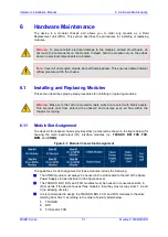
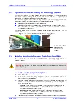
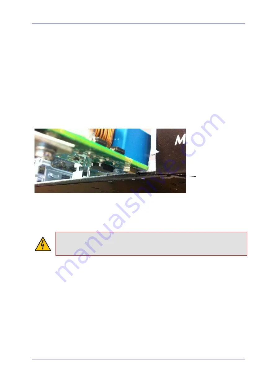
The figure below shows the correct orientation of the module when inserting it into the
chassis slot:
Figure
6-4: Incorrect Slot Insertion for Power Supply Module
6.1.4
Installing Modules into Previously Empty Front-Panel Slots
The procedure below describes how to install modules to previously empty slots in the
device's chassis.
Warning:
Ensure that you power down the device before installing a module to a
previously empty slot.
To install a module into a previously empty slot:
1.
Power off the device.
2.
On the device's front panel, using a Phillips screwdriver, remove the black metal cover
plate protecting the module slot.
3.
Insert the required module into the empty slot, aligning the module with the rails in the
slot in the following module orientation depending on whether you are inserting it in the
top- or bottom-row slots:
•
Top-row slots:
ensure that the module is orientated such that the port number
labels are located at the bottom of the module's front panel. This module
orientation is considered as facing up.
•
Bottom-row slots:
ensure that the module is orientated such that the port
number labels are located at the top of the module's front panel. This module
orientation is considered as facing down.
4.
Push the module into the slot and press on it firmly to ensure it has been fully inserted.
Component on Power
Supply Module
In Collision with
Chassis
Summary of Contents for Mediant 1000B
Page 1: ...Hardware Installation Manual Mediant 1000B MSBR Multi Service Business Router SIP Protocol ...
Page 2: ......
Page 12: ...Hardware Installation Manual 12 Document LTRT 40881 Mediant 1000B MSBR Reader s Notes ...
Page 14: ...Hardware Installation Manual 14 Document LTRT 40881 Mediant 1000B MSBR Reader s Notes ...
Page 34: ...Hardware Installation Manual 34 Document LTRT 40881 Mediant 1000B MSBR Reader s Notes ...
Page 70: ...Hardware Installation Manual www audiocodes com ...

