User's Manual
576
Document #: LTRT-10375
Mediant 500 MSBR
30.11.1 FXS Device Emulating PSAP using DID Loop-Start Lines
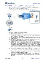
The device's FXS interface can be configured to emulate PSAP (using DID loop start lines),
according to the Telcordia GR-350-CORE specification.
Figure
30-13: FXS Device Emulating PSAP using DID Loop-Start Lines
The call flow of an E911 call to the PSAP is as follows:
1.
The E911 tandem switch seizes the line.
2.
The FXS device detects the line seize, and then generates a wink signal (nominal 250
msec). The wink can be delayed by configuring the parameter DelayBeforeDIDWink to
200 (for 200 msec or a higher value).
3.
The switch detects the wink and then sends the MF Spill digits with ANI and (optional)
Pseudo-ANI (P ANI).
4.
The FXS device collects the MF digits, and then sends a SIP INVITE message to the
PSAP with all collected MF digits in the SIP From header as one string.
5.
The FXS device generates a mid-call wink signal (two subsequent polarity reversals)
toward the E911 tandem switch upon either detection of an RFC 2833 "hookflash"
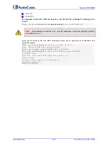
telephony event, or if a SIP INFO message with a "hooflash" body is received from the
PSAP (see the example below). The duration of this "flashhook" wink signal is
configured using the parameter FlashHookPeriod (usually 500 msec). Usually the wink
signal is followed by DTMF digits sent by PSAP to perform call transfer. Another way
to perform the call transfer is to use SIP REFER messages, as described below.
6.
The FXS device supports call transfer initiated by the PSAP. If it receives a SIP
REFER message with the Refer-To URI host part containing an IP address that is
equal to the device's IP address, the FXS device generates a 500-msec wink signal
(double polarity reversals), and then (after a user-defined interval configured by the
parameter WaitForDialTime), plays DTMF digits according to the transfer number
received in the SIP Refer-To header URI userpart.
7.
When the call is answered by the PSAP operator, the PSAP sends a SIP 200 OK to
the FXS device, and the FXS device then generates a polarity reversal signal to the
E911 switch.
Summary of Contents for Mediant 500 MSBR
Page 2: ......
Page 33: ...Part I Getting Started with Initial Connectivity ...
Page 34: ......
Page 36: ...User s Manual 36 Document LTRT 10375 Mediant 500 MSBR This page is intentionally left blank ...
Page 40: ...User s Manual 40 Document LTRT 10375 Mediant 500 MSBR This page is intentionally left blank ...
Page 45: ...Part II Management Tools ...
Page 46: ......
Page 48: ...User s Manual 48 Document LTRT 10375 Mediant 500 MSBR This page is intentionally left blank ...
Page 115: ...Part III General System Settings ...
Page 116: ......
Page 132: ...User s Manual 132 Document LTRT 10375 Mediant 500 MSBR This page is intentionally left blank ...
Page 137: ...Part IV General VoIP Configuration ...
Page 138: ......
Page 290: ...User s Manual 290 Document LTRT 10375 Mediant 500 MSBR This page is intentionally left blank ...
Page 306: ...User s Manual 306 Document LTRT 10375 Mediant 500 MSBR This page is intentionally left blank ...
Page 380: ...User s Manual 380 Document LTRT 10375 Mediant 500 MSBR This page is intentionally left blank ...
Page 454: ...User s Manual 454 Document LTRT 10375 Mediant 500 MSBR This page is intentionallty left blank ...
Page 455: ...Part V Gateway Application ...
Page 456: ......
Page 460: ...User s Manual 460 Document LTRT 10375 Mediant 500 MSBR This page is intentionally left blank ...
Page 484: ...User s Manual 484 Document LTRT 10375 Mediant 500 MSBR This page is intentionally left blank ...
Page 494: ...User s Manual 494 Document LTRT 10375 Mediant 500 MSBR This page is intentionally left blank ...
Page 625: ...Part VI Session Border Controller Application ...
Page 626: ......
Page 654: ...User s Manual 654 Document LTRT 10375 Mediant 500 MSBR This page is intentionally left blank ...
Page 656: ...User s Manual 656 Document LTRT 10375 Mediant 500 MSBR This page is intentionally left blank ...
Page 741: ...Part VII Cloud Resilience Package ...
Page 742: ......
Page 751: ...Part VIII Data Router Configuration ...
Page 752: ......
Page 753: ......
Page 754: ......
Page 756: ...User s Manual 756 Document LTRT 10375 Mediant 500 MSBR This page is intentionally left blank ...
Page 757: ...Part IX Maintenance ...
Page 758: ......
Page 834: ...User s Manual 834 Document LTRT 10375 Mediant 500 MSBR This page is intetnionaly left blank ...
Page 837: ...Part X Status Performance Monitoring and Reporting ...
Page 838: ......
Page 848: ...User s Manual 848 Document LTRT 10375 Mediant 500 MSBR This page is intentionally left blank ...
Page 852: ...User s Manual 852 Document LTRT 10375 Mediant 500 MSBR This page is intentionally left blank ...
Page 854: ...User s Manual 854 Document LTRT 10375 Mediant 500 MSBR This page is intentionally left blank ...
Page 878: ...User s Manual 878 Document LTRT 10375 Mediant 500 MSBR This page is intentionally left blank ...
Page 880: ...User s Manual 880 Document LTRT 10375 Mediant 500 MSBR This page is intentionally left blank ...
Page 926: ...User s Manual 926 Document LTRT 10375 Mediant 500 MSBR This page is intentionally left blank ...
Page 927: ...Part XI Diagnostics ...
Page 928: ......
Page 950: ...User s Manual 950 Document LTRT 10375 Mediant 500 MSBR This page is intentionally left blank ...
Page 954: ...User s Manual 954 Document LTRT 10375 Mediant 500 MSBR This page is intentionally left blank ...
Page 956: ...User s Manual 956 Document LTRT 10375 Mediant 500 MSBR This page is intentionally left blank ...
Page 958: ...User s Manual 958 Document LTRT 10375 Mediant 500 MSBR This page is intentionally left blank ...
Page 974: ...User s Manual 974 Document LTRT 10375 Mediant 500 MSBR This page is intentionally left blank ...
Page 976: ...User s Manual 976 Document LTRT 10375 Mediant 500 MSBR This page is intentionally left blank ...
Page 977: ...Part XII Appendix ...
Page 978: ......
Page 982: ...User s Manual 982 Document LTRT 10375 Mediant 500 MSBR This page is intentionally left blank ...


