Version 6.6
29
April 2012
Hardware Installation Manual
5. Cabling the Device
5.10 Connecting to Dry Contact Relay Alarm System
The dry contact ports
I
and
II
located on the device's CPU module allows you to connect
the device to an external audible or visual alarm system. The table below describes the
operational status of these dry contact ports.
Table
5-1: Dry Contact Operational Description
Port
Normal State
Alarm Severity State
I
During normal operation, the dry
contact is open.
If a Major alarm is generated, the
dry contact closes.
II
During normal operation, the dry
contact is closed.
If a Critical alarm is generated,
the dry contact opens.
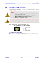
The external alarm system is connected to the device's dry contact connector on the CPU
module, using a dry contact wires mate consisting of a four spring-cage terminal block
connector (not supplied). The figure below shows an example of such a mate (labeled 4, 3,
2 and 1, from left to right). These connections correspond to the four pins of the dry contact
connector on the CPU module.
Figure
5-10: Example of a Dry Contact Wires Mate
Note:
It is recommended to use the dry contact mate of Phoenix Contact type FK-
MC 0,5/ 4-ST-2,5, or any other vendor providing similar specifications.
You need to supply your own wiring (for connecting to the mate’s spring-cage connections)
as well as a visual and/or audible alarm system attached at the other end of the wires. The
size of the cable gauge that connects to the dry contact ports must be in the range of 20 to
28 AWG. The dry contact system can receive a current of up to 1.5A. Its nominal switching
capacity is 2A 30V DC.
Note:
The dry contact alarm provided on the CPU must be connected only to SELV
(Safety Extra-Low Voltage) non-energy hazard sources (Class 2) as per UL
60950 and EN 60950.


