background image

Hardware Installation Manual 

18 

Document #: LTRT-85609 


Mediant 600 


3.1.5.2  LED Description 

The CPU module provides two  LEDs  for  each of the Ethernet ports  (located below the 
ports), as described in the table below: 


Table 


3-7: CPU Module LEDs Description 

LED 

Color 

State 

Description 

Left LED 

Orange 

Blinking 

Activity. 

Right LED 

Green 

On 

Link OK. 

Yellow 

Blinking 

Data is being received. 

Off 

No link. 


3.2 

Rear Panel Description 

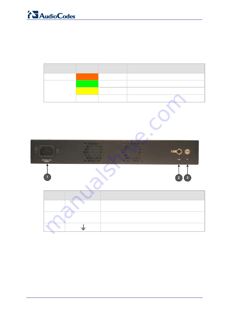
The device's rear panel is shown in the figure below and described in the subsequent table. 

Figure 


3-7: Rear Panel 


Table 


3-8: Rear-Panel Description 

Item # 

Label 

Component Description 

100 - 240V 0.5A


50-60Hz


AC power supply entry plug. 

ESD


Electrostatic Discharge (ESD) socket for attaching to an 
anti-static wrist strap and the ESD socket on the chassis.  


Protective earthing screw. 


Summary of Contents for Mediant 600

Page 1: ...Hardware Installation Manual Version 6 6 April 2012 Document LTRT 85609 MediantTM 600 VoIP Media Gateway SIP Protocol ...

Page 2: ......

Page 3: ...1 5 CPU Module 17 3 1 5 1 Port Description 17 3 1 5 2 LED Description 18 3 2 Rear Panel Description 18 4 Mounting the Device 19 4 1 Desktop Mounting 19 4 2 19 Inch Rack Mounting 20 5 Cabling the Device 21 5 1 Grounding the Device 21 5 2 Connecting to the IP Network 22 5 3 Connecting to FXS Interfaces 22 5 4 Connecting to FXO Interfaces 23 5 5 Connecting the Analog Lifeline Phone 24 5 6 Connecting ...

Page 4: ...Figure 5 4 RJ 11 Connector Pinouts for Analog Lifeline 24 Figure 5 5 Connecting the Analog FXS Lifeline 24 Figure 5 6 RJ 45 Connector Pinouts for BRI 25 Figure 5 7 PSTN Fallback for BRI Ports 26 Figure 5 8 RJ 48c Connector Pinouts for E1 T1 27 Figure 5 9 PSTN Fallback for PRI E1 T1 28 Figure 5 10 Example of a Dry Contact Wires Mate 29 Figure 5 11 RS 232 Cable Adaptor 30 List of Tables Table 3 1 Fr...

Page 5: ...hts reserved This document is subject to change without notice Date Published April 18 2012 Trademarks AudioCodes AC AudioCoded Ardito CTI2 CTI CTI Squared HD VoIP HD VoIP Sounds Better InTouch IPmedia Mediant MediaPack NetCoder Netrake Nuera Open Solutions Network OSN Stretto TrunkPack VMAS VoicePacketizer VoIPerfect VoIPerfectHD What s Inside Matters Your Gateway To VoIP and 3GX are trademarks o...

Page 6: ...specified the term device refers to the Mediant 600 gateway Warnings and Safety Information Note The device is an indoor unit and therefore must be installed only indoors Caution Electrical Shock Do not open or disassemble this device The device carries high voltage and contact with internal components may expose you to electrical shock and bodily harm Warning Disconnect the gateway from the mains...

Page 7: ...Introduction 1 Introduction This document provides a hardware description of the Mediant 600 hereafter referred to as device and step by step procedures for cabling the device Note For information on configuring the device refer to the device s User s Manual ...

Page 8: ...Hardware Installation Manual 8 Document LTRT 85609 Mediant 600 Reader s Notes ...

Page 9: ...carton 3 Check that there is no equipment damage 4 Ensure that in addition to Mediant 600 the package contains the following items One AC power cable Four anti slide bumpers for desktop installation option Two mounting brackets and four screws for 19 inch rack mounting Two meter length RS 232 DB 9 adaptor cable for direct serial connection to a computer 5 Check retain and process any documents If ...

Page 10: ...Hardware Installation Manual 10 Document LTRT 85609 Mediant 600 Reader s Notes ...

Page 11: ...ary Rate Interface PRI E1 T1 FXS interfaces and FXO interfaces and can be supplied in one of the following hardware configurations 1 x E1 T1 port can support also Fractional E1 T1 2 x E1 T1 ports 4 x BRI ports supporting up to 8 voice calls 8 x BRI ports supporting up to 16 voice calls 4 x BRI ports and 1 x E1 T1 port 4 x BRI and 4 x FXS ports 4 x BRI and 4 x FXO ports 4 x FXS ports and 1 x E1 T1 ...

Page 12: ...dules depends on the ordered configuration Table 3 1 Front Panel Description Item Label Component Description 1 FXS Optional FXS module see Section 3 1 1 on page 13 for a description FXO Optional FXO module see Section 3 1 2 on page 14 for a description BRI Optional BRI module see Section 3 1 3 on page 15 for a description TRUNKS Optional TRUNKS E1 TE J1 module see Section 3 1 4 on page 16 for a d...

Page 13: ...t FXS interfaces 3 1 1 1 Port Description Each FXS module provides up to four RJ 11 ports The ports are labeled I II III and IIII Figure 3 2 FXS Module 3 1 1 2 LED Description Each FXS port provides a LED for indicating operating status as described in the table below Table 3 2 FXS Module LED Description Color State Description Green On Phone connected to the port is off hooked Blinking Phone conn...

Page 14: ... interfaces 3 1 2 1 Port Description Each FXO module provides up to four RJ 11 ports The ports are labeled I II III and IIII Figure 3 3 FXO Module 3 1 2 2 LED Description Each FXO port provides a LED for indicating operating status as described in the table below Table 3 3 FXO Module LED Description Color State Description Green On Off hooks the line toward the PBX Blinking Detects a ring signal f...

Page 15: ... the device can support up to eight BRI interfaces 3 1 3 1 Port Description Each BRI module provides up to four RJ 45 ports The ports are labeled I II III and IIII Figure 3 4 BRI Module 3 1 3 2 LED Description Each BRI port provides a LED for indicating operating status as described in the table below Table 3 4 BRI Module LED Description Color State Description Green On Physical layer Layer 1 is s...

Page 16: ...2 LED Description Each trunk port provides a LED for indicating operating status as described in the table below Table 3 5 E1 T1 PRI TRUNKS Module LED Description Color State Description Green On Trunk is synchronized normal operation Red On Loss due to any of the following signals LOS Loss of Signal LOF Loss of Frame AIS Alarm Indication Signal the Blue Alarm RAI Remote Alarm Indication the Yello...

Page 17: ... bell siren hooter or light 2 II Dry contact port normally closed This can be connected to an external audible or visual alarm system bell siren hooter or light 3 Audio IN OUT Note This functionality will be supported in the next applicable release 4 I 10 100Base TX Ethernet port 5 II 10 100Base TX Ethernet port Note Two Ethernet ports provide Ethernet redundancy protecting against failure such as...

Page 18: ...king Activity Right LED Green On Link OK Yellow Blinking Data is being received Off No link 3 2 Rear Panel Description The device s rear panel is shown in the figure below and described in the subsequent table Figure 3 7 Rear Panel Table 3 8 Rear Panel Description Item Label Component Description 1 100 240V 0 5A 50 60Hz AC power supply entry plug 2 ESD Electrostatic Discharge ESD socket for attach...

Page 19: ...se rubber bumpers you can place it on a desktop where the bumpers are in contact with the surface Figure 4 1 Underside of Device with Rubber Foot To apply the anti slide rubber bumpers to the device 1 Flip the device over so that its underside faces up 2 Locate the four anti slide grooves on the device s underside one in each of the four corners as shown in the figure below Figure 4 2 Location of ...

Page 20: ...loading Consideration should be given to the connection of the equipment to the supply circuit and the effect that overloading of the circuits might have on over current protection and supply wiring Appropriate consideration of equipment nameplate ratings should be used when addressing this concern Reliable Earthing Reliable earthing of rack mounted equipment should be maintained Particular attent...

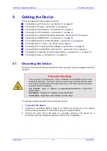
Page 21: ...11 on page 30 Connecting to power see Section 5 12 on page 31 5 1 Grounding the Device The device must be permanently connected to earth ground using an equipment earthing conductor Protective Earthing The equipment is classified as Class I EN60950 and UL60950 and must be earthed at all times The device must be permanently connected to the earth using the screw provided on the rear panel Use 14 16...

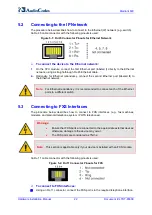
Page 22: ... II to the Ethernet network Note For Ethernet redundancy it is recommended to connect each of the Ethernet ports to a different switch 5 3 Connecting to FXS Interfaces The procedure below describes how to connect to FXS interfaces e g fax machines modems and plain old telephone system POTS telephones Warnings Ensure that FXS ports are connected to the appropriate external devices otherwise damage ...

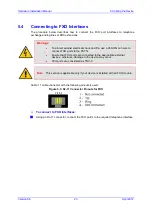
Page 23: ...6 AWG min wire to connect FXO ports to the PSTN Ensure that FXO ports are connected to the appropriate external devices otherwise damage to the device may occur FXO ports are considered as TNV 3 Note This section is applicable only if your device is installed with an FXO module An RJ 11 cable connector with the following pinouts is used Figure 5 3 RJ 11 Connector Pinouts for FXO To connect to FXO ...

Page 24: ...to the POTS phone as shown in the figure below Figure 5 4 RJ 11 Connector Pinouts for Analog Lifeline Notes Analog Lifeline is supported only on FXS modules An analog Lifeline can be setup for each FXS module installed in the chassis The scenarios i e power outage and or IP network loss upon which Lifeline is triggered is configured by the LifeLineType parameter For more information refer to the U...

Page 25: ...e is installed with a BRI module A BRI port can be configured either as TE Termination Equipment user side or NT Network Termination network side The connector pinouts vary according to the configuration as shown below Figure 5 6 RJ 45 Connector Pinouts for BRI When configured as NT the BRI port drives a nominal voltage of 38 V with limited current supply of up to 100 mA To connect to BRI lines 1 ...

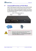
Page 26: ...connected to for example a PBX and its adjacent port is connected to an active PSTN line i e normal operation not only dedicated to Fallback In the event of a power failure a relay connects the adjacent BRI ports i e ports I to II and ports III to IIII by the closing of a metallic switch inside the module Figure 5 7 PSTN Fallback for BRI Ports Notes Damage can be caused to external equipment if PS...

Page 27: ...re use a 26 AWG min wire to connect T1 or E1 ports to the PSTN Note This section is applicable only if your device is installed with a TRUNKS module An RJ 48c trunk cable connector with the following pinouts is used Figure 5 8 RJ 48c Connector Pinouts for E1 T1 To connect the E1 T1 trunks 1 Connect the E1 T1 trunk cables to the device s RJ 48c ports 2 Connect the other ends of the trunk cables to ...

Page 28: ...e PSTN instead of from the PBX to the IP network To connect the digital trunk interfaces for PSTN Fallback Connect Port I to the PBX and Port II to the PSTN Figure 5 9 PSTN Fallback for PRI E1 T1 Notes Only ISDN supports the PSTN Fallback feature when the number of supported channels e g 30 is less than the maximum number of possible channels provided by the physical ports e g two E1 trunks When t...

Page 29: ...f a four spring cage terminal block connector not supplied The figure below shows an example of such a mate labeled 4 3 2 and 1 from left to right These connections correspond to the four pins of the dry contact connector on the CPU module Figure 5 10 Example of a Dry Contact Wires Mate Note It is recommended to use the dry contact mate of Phoenix Contact type FK MC 0 5 4 ST 2 5 or any other vendo...

Page 30: ...or light according to your preferences and requirements 5 11 Connecting RS 232 Serial Interface to a Computer The devices RS 232 interface port is used to access the CLI for serial communication and to receive error notification messages A 9 pin DB adaptor cable is supplied for connecting this port to a computer as described in the procedure below Figure 5 11 RS 232 Cable Adaptor To connect the de...

Page 31: ... made using the supplied AC power cord Warnings Units must be connected by service personnel to a socket outlet with a protective earthing connection Use only the AC power cord supplied with the device To connect the device to the power supply Connect the 100 240V 50 60 Hz power socket located on the device s rear panel to a standard electrical outlet using the supplied AC power cord ...

Page 32: ...Hardware Installation Manual www audiocodes com ...

Reviews: