Version 5.4
49
May 2008
SIP Hardware Installation Manual
3. Installation
•
Category 5 LAN cables with RJ-45 plugs (refer to the figure below):
Figure
3-5: RJ-45 LAN Ethernet Network Port and Connector
Table
3-1: RJ-45 Connector Pinouts for Gigabit Ethernet Interface
Pin
FE Signal
GE Signal
1
TX DATA+1
Tx A+
2
TX DATA-
Tx A-
3
RX DATA+2
Rx B+
4 N/C
Tx
C+
5 N/C
Tx
C-
6
RX DATA-
Rx B-
7 N/C
Rx
D+
8 N/C
Rx
D-
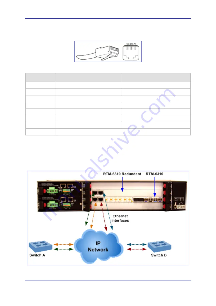
To provide full Ethernet redundancy in a Mediant 3000 High Availability system, it is
recommended to connect all four Ethernet interfaces (two on the RTM-6310 and two on the
RTM-6310 Redundant RTM) to the external IP network. In addition, to provide Ethernet
switch redundancy the two Ethernet ports on each RTM must be connected to different
switches, as illustrated in the figure below:
Figure
3-6: Cabling for LAN Redundancy in Mediant 3000 HA System Only


