RM500SL
®
User's Guide Version 3.4
June 2011
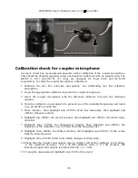
Coupling the hearing instrument
The Verifit is supplied with 2 metal couplers, a type HA-1 (ITE) and a type HA-2 (BTE).
Note
that an ANSI standard coupler for CICs does not exist.
These must be tested in the HA-1
coupler.
When threading the couplers onto the coupler microphone,
it is very important that they be
firmly tightened
to ensure a good acoustic seal. Avoid twisting the coupler microphone
cable – turn the coupler not the microphone or unplug the microphone while tightening the
coupler.
BTE
instruments are coupled to the HA-2 coupler by means of a 10 mm (3/8th “) length of
heavy wall #13 earmold tubing. The only purpose of this tubing is to seal the tip of the
earhook to the coupler inlet. All of the tubing required by ANSI S3.22 is machined into the
metal stem of the HA-2 coupler. The #13 tubing should be inspected regularly for cracks
which will cause feedback.
Custom
instruments are sealed to the HA-1 coupler with putty so that the end of the eartip
is flush with the inside of the coupler opening. Putty should not extend into the coupler
cavity or block the sound outlet of the instrument.
Vents should be sealed at the faceplate
end.
It is very important that the instrument be well-sealed to the coupler.
Open fit
instruments must use the coupler and coupling system specified by the
manufacturer. This may involve a hook that replaces the open fit tubing or an adapter tube
that may be sealed to the opening of the HA-1 coupler with putty.
RITE (Receiver in the ear)
instruments are coupled to the HA-1 coupler using putty to
seal the receiver module or soft tip to the coupler opening.
Excess low frequency output is usually due to open vents or a poor seal to the coupler.
For health reasons, hearing instruments should be clean before putty is applied and putty
should be replaced frequently.
Positioning the hearing instrument
1. The hearing instrument should be coupled to the appropriate coupler and a battery or
battery pill installed. See Coupling the hearing instrument and Battery pill use and care.
2. Place the instrument and coupler in the test chamber so that the microphone opening(s)
of the instrument are on the crossbar within the test zone.>>
3. Position the test box reference microphone as close as possible to the (front-facing)
microphone opening of the hearing instrument without touching it.
4. Close and seal the test chamber.
36
Summary of Contents for RM500SL
Page 1: ...RM500SL User s Guide Version 3 4 March 2010...
Page 9: ...RM500SL User s Guide Version 3 4 June 2011 EC Declaration of Conformity 9...
Page 10: ...RM500SL User s Guide Version 3 4 June 2011 10...
Page 37: ...RM500SL User s Guide Version 3 4 June 2011 37...
Page 43: ...RM500SL User s Guide Version 3 4 June 2011 telecoil test 43...
Page 51: ...RM500SL User s Guide Version 3 4 June 2011 51...
Page 57: ...RM500SL User s Guide Version 3 4 June 2011 57...
Page 64: ...RM500SL User s Guide Version 3 4 June 2011 64...
Page 78: ...RM500SL User s Guide Version 3 4 June 2011 Screen tour unaided screen 78...
Page 97: ...RM500SL User s Guide Version 3 4 June 2011 97...
Page 98: ...RM500SL User s Guide Version 3 4 June 2011 98...
Page 99: ...RM500SL User s Guide Version 3 4 June 2011 99...
Page 102: ...RM500SL User s Guide Version 3 4 June 2011 102...
Page 112: ...RM500SL User s Guide Version 3 4 June 2011 112...
Page 113: ...RM500SL User s Guide Version 3 4 June 2011 113...


