13
1
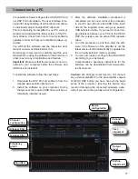
Line Input
FKDQQHOSUHDPSOL¿HULQSXWWRFRQQHFWVLJQDOVRXU
-
FHVVXFKDVUDGLRV,QSXWVHQVLWLYLW\LVVHWWRYROWV
,WLVSRVVLEOHWRYDU\WKHVHQVLWLYLW\RIHDFKFKDQQHO
IURPYROWVWRYROWVLQVLGHWKHGHYLFH
2
High Level Input
FKDQQHOKLJKOHYHOORXGVSHDNHULQSXW
Use this input to connect the processor directly to
loudspeaker outputs on an OEM or aftermarket ra-
GLRWKDWGRHVQRWKDYHDQ\SUHDPSOL¿HURXWSXWV
,QSXWVHQVLWLYLW\LVVHWWRYROWVIRUDOOFKDQQHOV
,WLVSRVVLEOHWRYDU\WKHVHQVLWLYLW\RIHDFKFKDQQHO
IURPYROWVWRYROWVLQVLGHWKHGHYLFH
Attention:
Solely use the pluggable screw-terminal
IRUWKHKLJKOHYHOFRQQHFWRUWKDWFRPHVZLWKWKHGH
-
YLFH
3
Optical Input
Optical input in SPDIF format for connecting signal
sources with a digital audio output. The sampling
rate of this input must be between 6 and 192 kHz.
The input signal is automatically adjusted to the in-
ternal sample rate.
,QRUGHUWRFRQWUROWKHYROXPHRIWKLVLQSXWZHUH
-
commend the optional cable remote control URC
$ $OWHUQDWLYHO\ D VLJQDO DSSOLHG WR WKH LQSXWV $
DQGRU%FDQEHXVHGWRFRQWUROWKHYROXPHRIWKH
optical input.
Notice:
7KLVDPSOL¿HUFDQRQO\KDQGOHVWHUHRLQSXW
signals and no Dolby-coded digital audio stream.
4
Power Input
This input is used for connecting the processor to
WKHSRZHUVXSSO\RIWKHYHKLFOHDQGIRUUHPRWHLQ
out.
,I WKH KLJKOHYHO ORXGVSHDNHU LQSXWV DUH XVHG WKH
remote input can be left unconnected. The remote
RXWSXWLVXVHGWRFRQWURODPSOL¿HUVZLWFKLQJRQDQG
RIIYLDWKHSURFHVVRU&RQQHFWWKLVUHPRWHRXWSXWWR
WKHUHPRWHLQSXWVRI\RXUDPSOL¿HU
Attention:
Solely use the pluggable screw-terminal
WKDWFRPHVZLWKWKHGHYLFH
Important:Never use a different signal than the
remote output of the DSP to activate connected
DPSOL¿HUV
5
Ground Lift Switch
The ground of the HELIX DSP signal inputs is gal-
YDQLFDOO\ GHFRXSOHG IURP WKH JURXQG RI WKH VLJQDO
outputs. In many cars this setup is the best way to
DYRLGDOWHUQDWRUQRLVH
1HYHUWKHOHVV WKHUH DUH XVH FDVHV ZKHUH LW ZLOO EH
necessary to directly connect input and output
JURXQG RU WR WLH ERWK JURXQGV WRJHWKHU YLD D UHVL
-
stor. Therefore the “Ground Lift Switch” has three
positions:
-
center position: input and output ground separa-
ted
-
left position: input and output ground tied toge-
ther
- right position: input and output ground con-
QHFWHGYLD2KPVUHVLVWRU
6
Control pushbutton
The control pushbutton allows the user to switch
between the two setup memory positions. Setups
ZLWK WKH H[WHQVLRQ ÄDI³ RU ³DF´ ZLOO EH DXWRPDWL
-
FDOO\ ZULWWHQ WR WKH ¿UVW VWRUDJH SRVLWLRQ ZKHUHDV
VHWXSVZLWKWKHH[WHQVLRQÄDI³RU³DF´ZLOOEHZULW
-
ten to the second storage position. To switch bet-
ween the setups, the button has to be pressed and
held for 1 second. Switching is indicated by a single
UHGÀDVKRIWKH6WDWXV/('
Pressing the button for 5 seconds completely era-
ses the internal memory. This is indicated by a con-
VWDQWÀDVKLQJRIWKH6WDWXV/('
Attention:
After erasing the setups from memory
the HELIX DSP will not reproduce any audio output.
7
Status LED
7KH 6WDWXV /(' LQGLFDWHV WKH FXUUHQW DFWLYH '63
setup. Green means that setup 1 (af1/ac1) is loa-
Initial start-up and functions


