background image

128-7410

19 of 20

Page 19

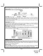
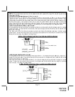
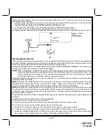
AFTER THE CONNECTION OF THE NEUTRAL START SAFETY WIRE AS INDICATED IN ANY OF THE PREVIOUS
ALTERNATE CONFIGURATIONS, THIS CIRCUIT MUST BE TESTED FOR OPERATION.
Retest by following the steps outlined in the NEUTRAL START SAFETY TEST shown in this manual.

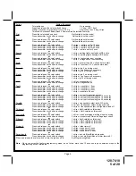
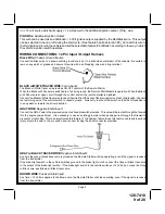
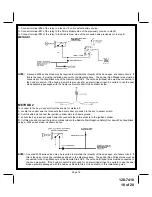
4 Pin Upgrade Telematic Module:
Red = + 5 Volts, Black = Ground, White = Data TX, Yellow = Data RX
If used, connect the 4 pin harness from the Telematic one way module kit to the mating port on the controlling circuit.
NOTE:  If using the TWO WAY Telematic module, only Ground, TX, and RX are used on this port, the + 12 volt supply
for the two way module must be sourced separately or the unit will not operate.

COMPLETING THE INSTALLATION:

After you have confirmed the operation of the Audiovox Remote Start unit and tested all the safety features of the
system:

1.  If you have not done so already, place the red rubber handle cover over the handle of the control switch for ease of

identification.  This will allow your customer to distinguish the Remote Start control switch from the program
switch.

2.  Mount the control module up and behind the dash securing it in place with cable ties or screws.  Be certain that the

chosen mounting location will not inhibit any of the controls of the vehicle.

3.  Securely harness and tie all wiring up and away from all hot and moving parts that they may come in contact with

under the dash board or in the engine compartment areas.

CAUTION: Particularly avoid the area around the steering shaft and column, as wires can wrap around these

mechanisms and impair the safe operation of the vehicle.

4.  Apply the Caution Labels supplied with this kit to a conspicuous area in the engine compartment.  Make sure to clean

the surface before affixing the label.

5.  Check the vehicle's wipers, lights, horn, etc.... to insure proper operation.

6.  Replace all panels that were removed during installation, and retest the system.

7.  Explain all activated features and safety systems associated with Remote Start Unit installed to the customer.

8. Place the Valet Switch Tag and or the Remote Start Control Switch Tag on their respective switches and

point these out to the customer.

Summary of Contents for 1287410

Page 1: ...4 Pin Output Harness 1 2 Pin Door Lock Harness 3 30 Amp In line Fuse Holders With Fuses 1 Control Switch 1 Plug In Push Button Programming Switch 1 Ring Terminal 4 1 2 Long Screws 1 Pin Switch 1 Remote Start Warning Label 1 Literature Package Model APS 905 Installation Manual 3 Channel Remote Start Keyless Entry System Installation Instructions This Unit Is Intended For Installation In Vehicles Wi...

Page 2: ...mmable Feature Bank 1 Is For Transmitter Programming See Transmitter Programming Guide RF Programmable Features Bank 2 Is Alarm Selectable Features Feature Selection 1 Chirp 2 Chirps 3 Chirps 4 Chirps 5 Chirps 6 Chirps 1st DoorL UL 1 Sec 3 5 Sec 1 Sec L Dbl U L Dbl L 1 Sec UL Dbl L Dbl UL 1 S l 350mS ul 2nd Accy Lock Auto Lock On Auto Lock Off 3rd Accy UL Auto UL All Auto UL Off 4th Headlights Not...

Page 3: ...e the valet switch 3 chirps auto unlock off Press transmitter Lock button to change 1 chirp Press transmitter Lock button to change 2 chirps auto unlock all doors or Fourth Press and release the valet switch Non Functional On This Unit or Fifth Press and release the valet switch Non Functional On This Unit or Sixth Press and release the valet switch Non Functional On This Unit or Seventh Press and...

Page 4: ... B4 Start 0 5V B4 Start 7th Ing 2 Select Off During Crank On During Crank Same As Accy 8th Ign 3 Select Off During Crank On During Crank Same As Accy 9th Diagnostics Off On 10th Crank Time 0 8 Sec 1 0 Sec 1 5 Sec 2 0 Sec 11th Gas Diesel Gas Diesel 10 Diesel 15 Diesel 20 12th Transponder O P While R S On During Start Until Ign Off 13th Temp Start Not Available 14th Crank Averaging Averaging Preset ...

Page 5: ... and release the valet switch 2 chirps crank time 1 0 sec Press transmitter Lock button to change 3 chirps crank time 1 5 sec Press transmitter Lock button to change 4 chirps crank time 2 0 sec Press transmitter Lock button to change 1 chirp crank time 0 8 sec or Eleventh Press and release the valet switch 1 chirp unit set for gasoline engine Press transmitter Lock button to change 2 chirps unit s...

Page 6: ...e drilled Carefully check behind the chosen location to insure the drill will not penetrate any existing factory wiring or fluid lines Drill a 1 4 hole in the desired location and thread the hood pin switch into it using a 7 16 nut driver or deep well socket If using the mounting bracket first secure the bracket to the desired location and secure the hood pin switch in the pre threaded mounting br...

Page 7: ...er to the ignition switch Separate feed wires must be used for the Red and Red White wires If your vehicle does not have two battery feed wires at the ignition switch then it is possible to connect both wires to the vehicle s battery This wire provides power for the start relay and the accessory relay I M P O R TA N T IT IS THE RESPONSIBILITY OF THE INSTALLING TECHNICIAN TO DETERMINE THE LOAD FACT...

Page 8: ...ons NOTE See programming information concerning this wire to allow output during the START mode VIOLET WIRE Accessory Output Connect this wire to the Accessory wire from the ignition switch This wire will show 12 volts when the ignition switch is turned to the ACCESSORY or ON and RUN positions and will show 0 volts when the key is turned to the OFF and START or CRANK positions WIRING THE 4 PIN ALT...

Page 9: ...re to one of the wires from the back of the previously mounted control switch Connect the remaining wire of the control switch to chassis ground Always try to mount the switch so that the ON position is in an upward or toward the driver direction GRAYWIRE NegativeInhibitInput1 Connect the GRAY wire to the previously mounted hood pin switch provided This wire will be routed through the firewall int...

Page 10: ...ther wire that it is presently connected to in the vehicle This wire provides a 12 Volt output when the ignition key is turned to the ON position and 0 Volts when the ignition key is OFF and when the vehicle is running under the control of the remote starter This wire should be connected to the ignition input of the alarm system The Yellow w Black wire output will allow you to remote start the veh...

Page 11: ...al 30 85 to a fused 12 volt battery source rated for a minimum of 25 Amp Connect terminal 87 to the third ignition wire in the vehicle C GM VATS Key Override If the vehicle has the General Motors VATS system installed you will need to bypass the system while the vehicle is operating under the control of the Remote Start Unit To Do This 1 Measure the resistance of the resistor pellet on the ignitio...

Page 12: ...HARNESS The auxiliary 4 pin connector provides low current outputs to control various functions in the vehicle during different stages of the Remote Start unit s operation Understanding these outputs and the time in which they occur will allow you to determine if they are needed for the particular vehicle you are working on as well as how to use them Black w Blue Trace Wire Pulsed Ground Output Be...

Page 13: ...provides a ground pulse during the arming sequence or pulsed ground lock output Connect the Red wire to the low current ground signal wire from the factory door lock switch to the factory door lock relay The Green wire of the 2 pin harness provides a ground pulse during the disarming sequence or pulsed ground unlock output Connect the Green wire to the low current ground signal wire from the facto...

Page 14: ...ended to allow the control of a transponder bypass interface module or transponder bypass relay The system also allows software selections to control the way in which this output operates see remote start feature 10 for setting this output When the unit is selected for output during the start sequence this output will be active at the same time Ign 3 becomes active and will remain active until the...

Page 15: ...le around any of the columns The Green Black wires should be connected to the negative terminal of the respective cylinder number which appears in any of the circles 2 For vehicles utilizing 2 cylinder firing per coil pack connect Green Black to the tach side of each coil pack For 8 cylinder four coil systems connect to any of the three coils 3 Connect the Yellow wire to a 12 volt ignition 1 sourc...

Page 16: ...the RF transmitter in an attempt to start the vehicle The car should not start 8 Repeat the above test this time move the gear selector to the drive position If the unit attempts to start failing this test recheck your Yellow Wire s connection This wire must be connected to the ignition switch side of the Neutral Start Switch If the vehicle you are working on does not have an Electrical Neutral Sa...

Page 17: ...operation of a vehicle utilizing an electrical neutral start switch and is inconsistent with the operator s manual Additional information concerning Key In Sensor methods 1 2 are listed below and should be reviewed before considering either alternative Method 1 will allow the safety required for the remote start unit and prevent the vehicle from starting while in any gear other than Park or Neutra...

Page 18: ...ow METHOD 2 To connect to the key in sensor circuit as shown for method 2 A Locate the control wire that connects the drivers door pin switch to the key in sensor switch B Cut this wire and connect the ignition cylinder side to chassis ground C Locate the key in sensor switch wire that connects the chime module to the ignition cylinder D Cut this wire and connect the ignition cylinder side to the ...

Page 19: ...our customer to distinguish the Remote Start control switch from the program switch 2 Mount the control module up and behind the dash securing it in place with cable ties or screws Be certain that the chosen mounting location will not inhibit any of the controls of the vehicle 3 Securely harness and tie all wiring up and away from all hot and moving parts that they may come in contact with under t...

Page 20: ...128 7410 20 of 20 Page 20 2005 Audiovox Electronics Corp Hauppauge NY 11788 128 7410 ...

Reviews: