background image

128-7827

11 of 20

11

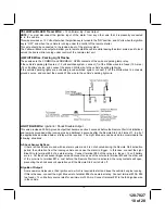
C. GM VATS Key Override:

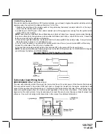
If the vehicle has the General Motors VATS system installed, you will need to bypass the system while the vehicle is
operating under the control of the Remote Start Unit.  To Do This;

1. Measure the resistance of the resistor pellet on the ignition key then select a resistor within 5% of the key's

value from the resistor pack supplied.

2. Locate the pair of VATS wires in the vehicle, usually a pair of thin gauge wires running from the ignition switch

to the VATS control module.

NOTE:

These wires are typically White w/ Black trace and Violet w/ Yellow trace, however in later model Cadillacs,

they are run through an orange sleeve, and are either both Black, both Yellow, or both White wires.  Consult the
factory service manual for additional information.
3. Connect the Light Blue Wire from the Remote Start Unit to terminal #86 of an external relay.  Connect terminal

#85 of the relay to a fused + 12 volt battery source.

4. Cut (#1) wire (as shown), and connect the ignition switch side of the cut wire to terminal #87a of the relay.
Connect the other side of the (#1) wire to terminal #30.
5. Connect the previously selected resistor from terminal #87 to the second (#2) wire (as shown).

NOTE:

The above information and following diagram is for the GM VATS system only.  For GM PASS LOCK System

you will require the Audiovox AS-PASS II Module.

General Motors VATS By-Pass Diagram

Tachometer Input Wiring Detail

GREEN/ORANGE  Wire: 

Tach Sensor Input

This wire will continually monitor the engine tach rate while the unit is under power of the Remote Start module.
This wire will be routed to the vehicle ECM tach input or through the firewall into the engine compartment and
connect to the negative side of the ignition coil.  This Remote Start unit learns the tach rate of the vehicle and in most
cases will operate properly from one multi coil pack regardless of the number of cylinders.  If the vehicle has a
single coil unit for each cylinder, it may be necessary to connect this wire to more than one cylinder for proper tach
reference.  See multi coil wiring detail shown later in this manual for additional information.

Summary of Contents for APS687 - Car Prestige Remote Start

Page 1: ...Chirp 2 Chirps 3 Chirps 4 Chirps 5 Chirps 6 Chirps 1st DoorL UL 1 Sec 3 5 Sec 1 Sec L Dbl U L Dbl L 1 Sec UL Dbl L Dbl UL 1 S l 350mS ul 2nd Accy Lock Auto Lock On Auto Lock Off 3rd Accy UL Auto UL D...

Page 2: ...unlock off Press transmitter Lock button to change 1 chirp 2 step unlock on or Eleventh Press and release the valet switch 2 chirps chirp delete from transmitter inactive Press transmitter Lock button...

Page 3: ...Starter 9th Diagnostics Off On 10th Crank Time 0 8 Sec 1 0 Sec 1 5 Sec 2 0 Sec 11th Gas Diesel Gas Diesel 10 Diesel 15 Diesel 20 12th Transponder O P While R S On During Start Until Ign Off 13th Temp...

Page 4: ...1 chirp ign 3 off during crank or Ninth Press and release the valet switch 1 chirp diagnostics off Press transmitter Lock button to change 2 chirps diagnostics on or Tenth Press and release the valet...

Page 5: ...hole must be drilled Carefully check behind the chosen location to insure the drill will not penetrate any existing factory wiring or fluid lines Drill a 1 4 hole in the desired location and thread t...

Page 6: ...r for the start relay and the accessory relay I M P O R T A N T IT IS THE RESPONSIBILITY OF THE INSTALLING TECHNICIAN TO DETERMINETHE LOAD FACTOR OF THE VEHICLES ELECTRICALCIRCUITS WHENTHE VEHICLE IS...

Page 7: ...0 volts when the key is turned to the OFF and ACCESSORY positions For Diesel Applications this wire must be connected to the ignition circuit that powers the glow plugs if the vehicle requires glow pl...

Page 8: ...being ground when the R S is activated This input is to be connected to a separate Other than the wire Red or Red White is connected to constant on 12 volt source which will supply 12 volt power to th...

Page 9: ...tter Ifthebrakelightswitchinthevehicleswitchesgroundtothebrakelightcircuit connecttheGrayw Blacktrace wire to the output of the brake light switch If the brake light switch in the vehicle switches 12...

Page 10: ...Ignition 3 Shock Disable Output This wire provides a 300mA ground output that becomes active 3 seconds before the Remote Start Unit initializes and remains grounded while running plus an additional 4...

Page 11: ...as shown and connect the ignition switch side of the cut wire to terminal 87a of the relay Connect the other side of the 1 wire to terminal 30 5 Connect the previously selected resistor from terminal...

Page 12: ...ock the vehicle doors if the doors unlock automatically when the factory anti theft system is disarmed Black w Red Trace Wire Pulsed Ground Output After Shutdown The Black w Red Trace wire will provid...

Page 13: ...f the channel 4 output NOTE This wire also can be used for defrost activation as dictated by the setting of feature 1 of Bank 3 Anytime the vehicle is running under control of the Remote Start and Cha...

Page 14: ...terminal 86 of the AS 9256 relay or an equivalent 30 Amp automotive relay and connect relay terminal 85 to a fused 12 VDC battery source Connect relay terminal 87 to the vehicle s horn switch output...

Page 15: ...tton switch on then turn the ignition key to the ON position 3 Thelightswillflashandthenumberofflasheswillindicatethereasonforshutdownonthelastremotestart attempt The indications are as follows 1 Flas...

Page 16: ...il returned to normal mode of operation This puts the unit into the R S Override mode indicating that the remote start is in the service mode and will not start from RF or any other input Posse or oth...

Page 17: ...CM Input or the vehicle key in sensor This connection will prevent remote start operation if the key is left in the ignition switch regardless of the gear selector position PARK NEUTRAL ECM INPUT The...

Page 18: ...circuit is not available METHOD 1 To connect to the key in sensor as shown in method 1 A Locate the control wire that connects the drivers door pin switch to the key in sensor switch B Cut this wire a...

Page 19: ...dule If you are using an Audiovox Flash Logic module it can be connected directly to the Alarm Remote Start s control module Using the Blue 4 pin blue red black white harness and connect to the mating...

Page 20: ...128 7827 20 of 20 20 2006 Audiovox Electronics Corp Hauppauge NY 11788 128 7827...

Reviews: