background image

Remote Car Starter

Installation Instructions

AS - 9151N

For installation in vehicles with 12 volt negative ground circuits,

gasoline engines, with automatic transmission only!

KIT CONTENTS

(1) Remote Start Control Module
(2) Wiring Harnesses
(1) Parts Bag Containing

(2) Fuses
(2) Fuse Holders
(1) Control Switch

(1) Hood Diode Bridge
(1) Literature Package
(1) RF Antenna Extender (AS-9166)

Form No. 128-4500B

(1) Ring Terminal
(4) 1/2" Long Screws
(1) Pin Switch

Summary of Contents for AS - 9151N

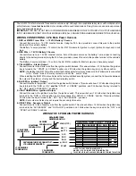
Page 1: ...cuits gasoline engines with automatic transmission only KIT CONTENTS 1 Remote Start Control Module 2 Wiring Harnesses 1 Parts Bag Containing 2 Fuses 2 Fuse Holders 1 Control Switch 1 Hood Diode Bridge 1 Literature Package 1 RF Antenna Extender AS 9166 Form No 128 4500B 1 Ring Terminal 4 1 2 Long Screws 1 Pin Switch ...

Page 2: ...ter Output Connect this wire to the starter wire from the ignition switch harness This wire will show 12 Volts when the ignition key is turned to the START or CRANK position and 0 Volts when the ignition key is in any other position NOTE If installing the AS 9151N with an alarm that utilizes a starter cut relay make sure the Yellow wire is connected to the starter side of the relay contacts and no...

Page 3: ...ded the Remote Starter will stop operating even if the signal is received from the alarm IMPORTANT If the alarm system does not incorporate a hood pin switch you must add a switch to the Remote Start system This is an important safety feature of the AS 9151N Remote Starter and failure to use this feature can result in serious injury 5 GREY w BLACK Tracer Wire Negative Inhibit Input 2 Any time the ...

Page 4: ...85 of the relay to a fused 12 Volt battery source Cut the trigger wire from the shock sensor and connect one side of the cut wire to terminal 30 of the relay Connect the other side of the cut wire to terminal 87a of the relay Just before the remote starter is activated the relay contacts will open and the shock sensor will not trip the alarm B Ignition 3 Output Some newer vehicles use a third igni...

Page 5: ...out the firing order of the engine in groups as indicated below Draw a circle around any of the columns The Green Black wires should be connected to the negative terminal of the respective cylinder number which appears in any of the circles 2 For vehicles utilizing 2 cylinder firing per coil pack connect Green Black to the tach side of each coil pack For 8 cylinder four coil systems connect to any...

Page 6: ...ened is the transmission in park are the brake lights on etc B If the starter motor cranked but engine did not start check the connection and location of the Light Blue primary ignition wire C If the lights turned on but the starter motor did not crank check the connection and location of the Yellow start wire COMPLETING THE INSTALLATION 1 Mount the control switch in the passenger compartment wher...

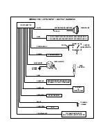
Page 7: ...SE CHANNEL2OR3 OUTPUTFROMALARM NEGATIVEINHIBIT2 TACH HOOD PINSWITCH SPLICE EXISTING BRAKESWITCH IGNITION3 O R SHOCKBY PASS TOCHASSIS GROUND EXISTINGPARKINGLAMPWIRE SPLICE PARKINGLAMP BROWNw BLACK BROWN BLACKw WHITE CHASSIS GROUND GREY DARKBLUE GREYw BLACK BLACK DARKGREEN YELLOWw BLACK TO 12VOLTBATTERYFORPOSITIVESWITCHEDPARKINGLIGHTS TOCHASSISGROUNDFORNEGATIVESWITCHEDPARKINGLIGHTS ...

Reviews: