• Safety Check after Servicing
Examine the area surrounding the repaired location for damage or deterioration. Observe that screws, parts and wires
have been returned to original positions. Afterwards, perform the following tests and confirm the specified values in
order to verify compliance with safety standards.
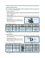
1. Insulation resistance test
Confirm the specified insulation resistance or greater between power cord plug prongs and externally exposed parts
of the set (RF terminals, antenna terminals, video and audio input and output terminals, microphone jacks, earphone
jacks, etc.). See table below.
2. Dielectric strength test
Confirm specified dielectric strength or greater between power cord plug prongs and exposed accessible parts of the
set (RF terminals, antenna terminals, video and audio input and output terminals, microphone jacks, earphone jacks,
etc.) See table below.
3. Clearance distance
When replacing primary circuit components, confirm
specified clearance distance (d), (d') between soldered
terminals, and between terminals and surrounding
metalic parts. See table below.
Table 1: Rating for selected areas
* Class
II
model only.
Note: This table is unofficial and for reference only. Be sure to confirm the precise values for your particular country
and locality.
4. Leakage current test
Confirm specified or lower leakage current between B (earth ground, power cord plug prongs) and externally
exposed accessible parts (RF terminals, antenna terminals, video and audio input and output terminals, microphone
jacks, earphone jacks, etc.)
Measuring Method: (Power ON)
Insert load Z between B (earth ground, power cord plug
prongs) and exposed accessible parts. Use and AC
voltmeter to measure across both terminals of load Z.
See figure and following table.
Table 2: Leakage current ratings for selected areas
Note: This table unofficial and for reference only. Be sure to confirm the precise values for your particular country and
locality.
Z
Exposed
accessible
part
AC Voltmeter
(high impedance)
Earth Ground
power cord plug prongs
B
Fig. 2
AC Line Voltage
Region
Insulation
Dielectric
Clearance
Resistance
Strength
Distance (d), (d')
100V
Japan
≥
1 M
Ω
/500 V DC
1kV 1 minute
≥
3 mm
110 to 130V
USA &
– – –
900V 1 minute
≥
3.2mm
Canada
* 110 to 130 V
Europe
≥
10 M
Ω
/500 V DC
4 kV 1 minute
≥
6 mm (d)
200 to 240 V
Australia
≥
8 mm (d')
(a: Power cord)
Fig. 1
d
Primary circuit terminals
Chassis
d'
a
AC Line Voltage
Region
Earth Ground
Load Z
Leakage Current (i)
(B) to:
100V
Japan
¡
≤
1m A rms
Exposed accessible
parts
110 to 130 V
USA &
¡
≤
0.5 m A rms
Exposed accessible
Canada
parts
¡
≤
0.7 m A peak
Antenna earth
110 to 130 V
Europe
¡
≤
2 m A dc
terminals
200 to 240 V
Australia
¡
≤
0.7 m A peak
Other terminals
¡
≤
2 m A dc
1k
1.5k
1.5kµF
2k
50k
Summary of Contents for AVP-7180
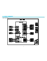
Page 16: ...3 2 CIRCUIT DIAGRAMS 15 1 CONNECTION DIAGRAM...
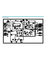
Page 17: ...16 2 POWER CIRCUIT DIAGRAM...
Page 19: ...18 3 SERVO SYSCON CIRCUIT DIAGRAM...
Page 21: ...20 4 VIDEO NOR AUDIO CIRCUIT DIAGRAM...
Page 23: ...22 5 Hi Fi PRE AMP CIRCUIT DIAGRAM...
Page 24: ...23 6 A V IN OUT CIRCUIT DIAGRAM...
Page 42: ...41 3 TIMING CHART OF S1 MECHA MECHANISM...
Page 46: ...45 B Deck bottom view...
Page 50: ...SKETCH OF JIGS AND TOOLS 49...
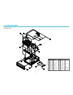
Page 70: ...4 6 EXPLODED VIEW OF DECK AREA AND PARTS LIST 69 1 EXPLODING VIEW OF THE DECK...
Page 71: ...70...
Page 74: ...AUDIOVOX SPECIALTY MARKETS CO LP 23319 COOPER DR ELKHART IN 46514 219 266 1886...


