background image

9

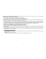
GENERAL VEHICLE INSTALLATION APPROACH

1.  Decide upon the system configuration and options that will be installed.
2.  Review all manuals to become familiar with electrical requirements and hookups.
3.  Decide upon the mounting locations of all components and the method of mounting.
4.   Prep the vehicle. Remove any interior trim necessary to gain access to vehicle's wiring, as well as all areas where interconnecting wire harnesses 

will be located. If any access holes need to be cut into the vehicle, do this now.

5.   Route the wiring harnesses in the vehicle as necessary. Refer to the wiring diagrams in this manual, as well as the wiring instructions for the 

individual components and accessory options being installed. Ensure that the wiring is protected from sharp edges. Ensure that all wiring is not 
pinched when all components and interior trim are fully installed. Leave enough slack in the wiring at each component to allow working room.

6.  Remove all A/V system components from their packaging and place them loosely in the vehicle at their respective locations.
7.   Connect all components together and verify the proper operation of all system functions. 


Note: 

This is best done BEFORE components have been permanently mounted.

8.  After verifying proper operation of the system, proceed to mount each component.
9.   When all components are mounted, recheck the function of the entire system. Ensure that no wiring was pinched or connected improperly during  

final installation

10.  Dome light wiring must be carefully planned due to the design of vehicle electrical systems.  Some vehicles use an electronic module (i.e. Body 

Control Module) to turn the dome lights on and off.  Care must be used to avoid damage to these types of electronic modules or damage to 
the dome light circuit in the DVD overhead.

General guidelines for dome lamp wiring:
1.   If it is not certain how the dome lamps tie into the vehicle electrical system, wire the dome lamp circuit (of the DVD overhead) to the driver’s 

door pin switch.

2.  Follow the instructions on page 11 and 12.
3.  Contact the Audiovox tech support line if you have any questions regarding dome lamp wiring.

Summary of Contents for AVXMTG13UA

Page 1: ...13 3 Inch LED Backlit LCD Roof Mount DVD Player With DVD CD MP3 SYSTEM AVXMTG13UA INSTALLATION GUIDE ...

Page 2: ...ge 4 Removing and Installing Snap On Covers and Shroud 5 Installing the Trim Ring 8 General Vehicle Installation Approach 9 Vehicle Preparation 10 Connecting the Dome Lights 11 Installing the Mounting Bracket 13 Wiring the AVXMTG13UA Video System 14 Installing the AVXMTG13UA Video System 15 Troubleshooting 16 1 ...

Page 3: ...le is in gear or when the parking brake is not applied must be installed to the rear of the driver seat where it will not be visible directly or indirectly to the operator of the motor vehicle WARNINGS t Do not use any solvents or cleaning materials when cleaning the video monitor t Do not use any abrasive cleaners they may scratch the screen t Use only lightly dampened lint free cloth to wipe the...

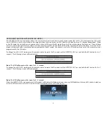
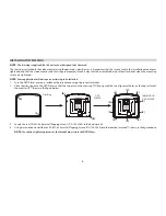
Page 4: ...control programmed to the M1 mode Conversely a unit set to M1 mode will not work with a remote control programmed to the M2 mode To change from M1 to M2 mode point the remote control towards the IR receiver on the AVXMTG13UA Press and hold the M2 button for 5 to 7 seconds The following screen will be displayed Note The OSD will appear on the screen for 4 5 seconds To change from M2 to M1 mode poin...

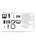
Page 5: ...xtreme caution when using these screws to avoid damage to vehicle roof or other components wiring etc 5 Remote Control P N 136 5185 1 pc 6 Mounting Bracket P N 108 4087 1 pc 7 Snap on Shroud Pewter P N 172 0191 1 pc Shale P N 172 0190 1 pc 8 Snap on Screen Cover Pewter P N 172 0189 1 pc Shale P N 172 0188 1 pc 9 Pry Tool P N 100 2565 1 pc 10 3 5mm 3RCA Jack pigtail P N 112 4143 1 pc 11 Trim Ring B...

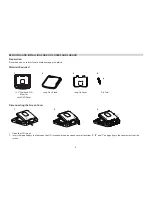
Page 6: ...tic Materials Required Disconnecting the Screen Cover 1 Open the LCD screen 2 Insert the supplied pry tool between the LCD screen and snap on screen cover at locations A B and C and gently pry the cover away from the screen 13 3 Overhead LCD Monitor with DVD Player Snap On Shroud Snap On Cover Pry Tool 1 2 3 4 1 2 3 A B C C ...

Page 7: ... edge of the screen cover into the notches on the bottom edge of the LCD screen 3 Snap the opposite side of the screen cover over the hinges 1 Open the LCD screen 2 Insert the supplied pry tool between the unit and shroud at fastener locations E and gently pry the shroud away from the unit D D D D 1 2 E Fasteners ...

Page 8: ...7 Installing the Shroud 1 Open the LCD screen 2 Slide the shroud over the unit The shroud will snap into place at locations F F F 1 2 ...

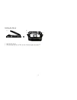
Page 9: ...d INSTALLING THE TRIM RING 8 1 Turn the DVD Player over on a surface with protective covering to prevent scratches 2 Place the trim ring onto the DVD Player so that the two pins on the trim ring A line up with the two alignment holes on the top surface of the monitor B shown in the figure below 3 Locate the ten 10 M2 6 x 6mm Self Tapping Screws P N 100 2568 in the hardware kit 4 Usingascrewdriver ...

Page 10: ... system components from their packaging and place them loosely in the vehicle at their respective locations 7 Connect all components together and verify the proper operation of all system functions Note This is best done BEFORE components have been permanently mounted 8 After verifying proper operation of the system proceed to mount each component 9 Whenallcomponentsaremounted recheckthefunctionof...

Page 11: ...the video monitor is where the vehicle s factory dome light is installed The monitor should be located in such a manner that it can be comfortably viewed by rear seat passengers NOTE NEVER INSTALL THE MONITOR IN A PLACE WITHIN THE DRIVER S VIEW THIS IS NOT ONLY DANGEROUS BUT IT IS ALSO ILLEGAL IN MANY STATES 4 Once the mounting location of the monitor has been determined additional preparation wor...

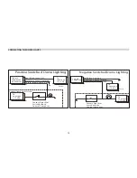
Page 12: ...he Purple Brown Lamp Auto wire to the vehicle s switched wire Then connect the Red Black Lamp ON wire to a fused constant 12 volt source and the Black Red Lamp Common wire to a good ground Positive switched systems are commonly found on Ford vehicles For negative switched systems connect the Purple Brown Lamp Auto wire to the vehicle s switched wire Then connect the Red Black Lamp On wire to a goo...

Page 13: ...ack Red Lamp Common Purple Brown Lamp Auto Positive Switched Dome Lighting Fused Factory Dome Light Circuit To 3 pin connector To constant Factory Door Ajar Switch or Body Control Computer Red Black Lamp on Black Red Lamp common Purple Brown Lamp Auto To constant 12 VDC 12 VDC Negative Switched Dome Lighting Fused CONNECTING THE DOME LIGHTS ...

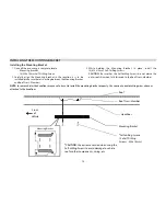
Page 14: ...x 15mm Self Drilling Screws CAUTION Be sure that the Self drilling Screws do not pierce the outer roof skin when fully fastened to the Roof Cross Member Self drilling Screws Mounting Bracket Headliner Roof Cross Member Roof 4 x Self Drilling Screws M4 x 15mm Mounting Bracket CAUTION Use extreme caution when using the Self drilling Screws to avoid damage to vehicle roof or other components wiring e...

Page 15: ...he RCA output connectors on the 12 pin harness to the input of an optional external monitor 5 Verify all system functions before final mounting of the finished assembly A V Source Definitions t AV Signal Harness to the 3 RCA Jack Pigtail is used for AV input P N 112 4143 t DVD Built in DVD t USB USB Input t CARD SD Card input AV output Rear of Unit Headphone Jack 112 4126 112 4143 112 4129 Antenna...

Page 16: ...STALLING THE AVXMTG13UA VIDEO SYSTEM Mounting Bracket Headliner Roof 4 x M5 Screws Video Unit Front of Vehicle Mounting Bracket MountingHoles CAUTION The 15mm 25mm and 40mm screws 4 each in the hardware kit are provided to facilitate installation Use extreme caution when using these screws to avoid damage to vehicle roof or other components wiring etc 15 ...

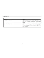
Page 17: ...a ground connection with a continuity test from a known good ground to the black wire at the 2 Pin Power Harness Power but no video or sound Verify that the correct source is selected i e 1 2 3 or 4 Verify that the source is on and playing a known good media such as a videotape Verify the connections at both ends of the source component harness ...

Page 18: ... 2010 AUDIOVOX 150 Marcus Blvd Hauppauge NY 11788 128 9214 www audiovoxproducts com 2013 AUDIOVOX 150 Marcus Blvd Hauppauge NY 11788 ...

Page 19: ...13 3 Inch LED Backlit LCD Roof Mount DVD Player With DVD CD MP3 SYSTEM AVXMTG13UA OPERATION MANUAL ...

Page 20: ...eive Modes M1 or M2 4 Controls and Indicators Diagram 5 Remote Control Operation 7 DVD Basics 11 Loading and Playing Discs 13 Settings and Adjustments 13 Playing JPEG Files 17 Playing MP3 Files 18 Wireless FM Modulator 18 Source Features 19 Troubleshooting 21 Specifications 23 Notes 24 1 ...

Page 21: ...where it will not be visible directly or indirectly to the operator of the motor vehicle WARNINGS t Do not use any solvents or cleaning materials when cleaning the video monitor t Do not use any abrasive cleaners they may scratch the screen t Use only lightly dampened lint free cloth to wipe the screen if it is dirty t Lock the LCD screen in fully closed position when not in use t Before putting o...

Page 22: ...ct to ensure that you obtain the best results from your equipment t 13 3 TFT LCD monitor t LED Backlight t Built in DVD Player t Selectable A and B IR receive and transmit modes t Multi Lingual On Screen Display OSD for control of picture quality and functions t Audio Video source inputs t Dome lights with built in three way switch t Last Position Memory for DVD t Built in 16 channel frequency wir...

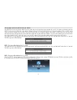
Page 23: ...ote control programmed to the M1 mode Conversely a unit set to M1 mode will not work with a remote control programmed to the M2 mode To change from M1 to M2 mode point the remote control towards the IR receiver on the AVXMTG13UA Press and hold the M2 button for 5 to 7 seconds The following screen will be displayed NOTE This screen will be displayed for 4 5 seconds To change from M2 to M1 mode poin...

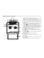
Page 24: ...this button to release the LCD screen from its locked position The screen will drop down slightly Pivot the screen downward until a comfortable viewing angle is reached 8 POWER Button Press this button to turn the system on or off The button is lit blue when power is available 9 FMM Button Turns the wireless FM Modulator FMM on or off 10 EJECT Button Press this button to eject a disc from the disc...

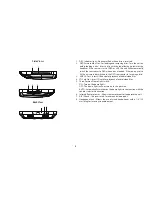
Page 25: ...D source prior to inserting a disc 3 USB 2 0 Port Insert USB device for playback of audio video files 4 SD Card Slot Insert SD card for playback of audio video files 5 Three Position Dome Light Switch ON Turn on the dome lights OFF The dome lights will not turn on in this position AUTO Automatically switches on the dome lights in conjunction with the vehicle s interior illumination 6 Infrared Remo...

Page 26: ...tom of the remote Back View Battery Replacement 1 Depress the tab 1 and slide the battery holder 2 out in the direction of the arrow 2 Install one CR2025 battery Make sure that the proper polarity or is observed 3 Slide the battery holder into the remote control until it locks Protective Pull Tab Clear Plastic Tab 1 Battery Holder 2 1 2 ...

Page 27: ...g 8 NEXT DOWN CURSOR Button Go to the next chapter or track The cursor is used to select menus on the screen 9 A B Button Allows the user to repeat the playback from point A to point B Press A B Button Once Repeat A Marks the beginning of the section to repeat set point A Press A B Button Twice Repeat AB Marks the end of the section to repeat set point B Press A B Button a Third time Repeat Off Ca...

Page 28: ...justment when using the Pic button 16 SUBTILE Button Press to display and select an available subtitle language in DVD mode 17 SCREEN MODE SELECTION Button Press this button to switch between Wide 16 9 or Normal 4 3 aspect ratios 18 AUDIO Button Press this button to display and select an available audio language in DVD mode 19 DISPLAY Button Press this button to display current disc information wh...

Page 29: ...ton to display the setup menu The setup menu allows the user to change DVD player options such as OSD LANGUAGE PARENTAL CONTROL etc 26 RETURN Button Press Return Once Go to disc menu Press Return Twice Go to movie playback 27 ANGLE Button Press this button to display and select different camera angles in DVD mode Not all discs contain this option Press this button to change between color mode and ...

Page 30: ...isc to play If the region codes do not match the disc will not play This system is set to Region 1 USA and will not play discs that have a region code different from Region 1 The system will display WRONG REGION Region 1 USA Canada Region 2 Japan Europe South Africa Middle East Greenland Region 3 South Korea Taiwan Hong Kong Parts of South East Asia Region 4 Australia New Zealand Latin America inc...

Page 31: ...s JPEG picture files This unit is capable of playing most recordable DVD formats However due to the variety of disc manufacturers and software playback can not be guaranteed for every disc Disc Compatibility Before a disc is loaded make sure that it is compatible with the player The following discs can not be played with this player t MiniDisc t Laserdisc t CD I CD ROM DVD ROM Super Audio CD SACD ...

Page 32: ... use The General Password or Preference Setup Page menus contains features and options that let you customize your DVD player For example the user can choose a language for the On Screen Display OSD or control DVD playback content for children Main Menu 1 Press the SETUP button The Main Menu will appear on the screen 2 Press the WW or XX button to select the General Password or Preference Setup Pa...

Page 33: ... you to select different camera angles in DVD playback Optional settings On Off The default setting is Off NOTE The number of angles vary from disc to disc Not all discs contain this option General AngleMark TVType OSDLang ScreenSaver Wide Off NTSC ENG ON Pal NTSC General General Setup Page Set TV Standard Password Preference Exit TV Type This item allows the user to select a TV type Optional Sett...

Page 34: ...s the user to set a four number password 1 Select the Change option 2 Press the OK button The Change Password screen appears NOTE The default password is 3308 This password is always accepted even after a new password has been entered To avoid the possibility of others using the default password to change passwords record this default password in another area and delete it from this manual General...

Page 35: ...o be changed during playback by pressing the Subtitle button Audio Subtitle DiscMenu Parental Default ENG Off ENG English French Spanish Italian General Preference Page Prefered Menu Language Password Preference Exit Disc Menu This item allows the user to choose the menu language stored on the disc Optional Settings English French Spanish Italian The default setting is English NOTE This function i...

Page 36: ... or cursor buttons to navigate up and down or the WW XX cursor buttons to navigate left and right through the thumbnails Press the OK button to view the picture 8 When viewing files may appear when pressing Subtitle or Audio etc In this situation these options are unavailable Preference Page Menu continued Audio Subtitle DiscMenu Parental Default ENG Off ENG Reset General Preference Page Load Fact...

Page 37: ...lows the user to listen to audio through the vehicle s radio To choose a FM frequency for audio playback through the vehicle s radio 1 Select a station between 88 1 and 91 1 that is not used by a broadcasting radio station 2 On the remote control press the FMM ON OFF button until FM ON appears on the screen 3 Press the CHANNEL SELECT button to select the FM Modulator frequency Choose a frequency n...

Page 38: ...d then on and the DVD disc is not removed the unit will play the DVD from the point it stopped last time AV The unit will accept an audio video input through the AV In jack located on the rear of the unit The audio video device can be a video game system video camera or other input device A 3 5mm to RCA Adapter is supplied for this option USB Insert a USB device located on the side on the unit and...

Page 39: ...icle interior lighting Refer to the installation guide for wire connections Do not leave the vehicle unattended with the dome light switch in the ON position as this could discharge the battery Infrared Remote Sensors The unit incorporates two infrared remote sensors which relay signals from the remote control to allow the unit to be controlled Optional IR Headphones Optional IR infrared headphone...

Page 40: ... If using 2 channel IR headphones make sure the correct channel A B is selected See page 4 3 Make sure the modulator is ON and the proper frequency has been selected on the vehicle s radio 4 Make sure the audio is not muted See page 9 5 Make sure the IR Transmitter is turned ON See page 9 Can t advance through a movie 1 The user is unable to advance through the opening credits and warning informat...

Page 41: ...22 Problem Solution Picture is distorted 1 The disc might be damaged try another disc 2 It is normal for some distortion to appear during forward or reverse scan ...

Page 42: ...reen Resolution 1280 x 3 RGB x 800 Operation Temperature 32 to 140 F 0 to 60 C Storage Temperature 4 to 158 F 20 to 70 C Backlight LED Power Source 12 VDC Video Display System NTSC PAL Headphone Audio Output 5mw 32 ohms Video Output 1 0 Vpp 75 ohms ...

Page 43: ...24 NOTES ...

Page 44: ...by removal or defacement of the factory serial number bar code label s THE EXTENT OF THE COMPANY S LIABILITY UNDER THIS WARRANTY IS LIMITED TO THE REPAIR OR REPLACEMENT PROVIDED ABOVE AND IN NO EVENT SHALL THE COMPANY S LIABILITY EXCEED THE PURCHASE PRICE PAID BY PURCHASER FOR THE PRODUCT This Warranty is in lieu of all other express warranties or liabilities ANY IMPLIED WARRANTIES INCLUDING ANY I...

Page 45: ... 2013 AUDIOVOX 150 Marcus Blvd Hauppauge NY 11788 128 9213 www audiovoxproducts com ...

Page 46: ...our customer service staff stands ready to help Contact us at www audiovox com t PURCHASE REGISTRATION Registering On line will allow us to contact you in the unlikely event asafety notification is required under the Federal Consumer Safety Act L AUDio o ELECTRONICS CORP Register Online at WWW AUDIOVOX COM Click on Product Registration and Fill Out the Brief Questionnaire ...

Page 47: ...igne sur WWW AUDIOVOX COM Cliquez sur Enregistrement produit et remplissez le court questionnaire ENREGISREGISTRO DEL PRODUCTOTREMENT DU PRODUIT Gracias porcon 111IJI IIIIul AudlcMJx Nos1111J9IIece Ia calldad Yftabllldad de todos 111811nJs produi D eleclr6nicos pero sl algllla vezII8C8Sita servlclos16cnlcososl tiene algllla pragunla lll8llrO personal de alllnCI6n al clln 8116 asu disposlcl6n para ...

Reviews: