8
F. Controls, Indicators, and Connectors
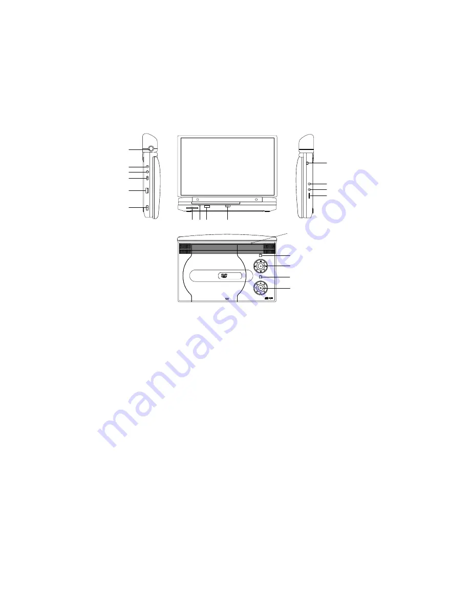
1. Unit View
(Refer to Figure 3)
Figure 3
* Connecting to headphone jack number 1 will disable the
internal speakers
1
2
3
4
5
7 8 9
10
11
12
13
14
15
16
17
18
19
6
1) Release Button of Battery
2) DC 9-12V Input Jack
3) AV Jack
4) AV In/Out SW
5) USB Port
6) Power On/Off SW
7) SD/MMC/MS Slot
8) Power LED
9) Remote Control Sensor
10) Cover Open Switch
11) Charge Indicator
12) Headphone Jack 1*
13) Headphone Jack 2
14)Volume Control
15) LCD Panel shut off
16) Wide Button
17) Previous/Next/Pause/Stop/Play
18) Menu Button
19) Up/Down/Left/Right/OK Button


