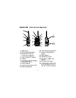
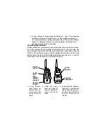
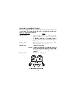
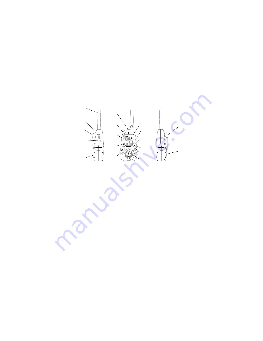
background image

4

1. Battery Door
2. Monitor/Backlight Button
3. Detachable Carry Clip

Part Number 2VMKBLT

4. Push-To-Talk (PTT) Button
5. Antenna
6. External Speaker(SPK)/Micro-

phone (MIC) Jacks

7. Built-in Speaker
8. Liquid Crystal Display (LCD)
9. Built-in Microphone

GMRS2VMK   (FCC License Required)

10. Up Channel/Volume Button
11. Down Channel/Volume

Button

12. MODE Button
13. SCAN/Lock Button
14. Emergency (EMG) Call

Button

15. Power On/Off Control
16. Combination Transmit Indi-

cator (Red)/Receive  and
Monitor Indicator (Green)
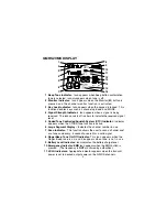
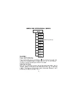
SCAN

EMG

MODE

EMG

ID

CTC

OUT OF
RANGE

EMG

OUT OF
RANGE

HI  LO

HI  LO

CTC  ID

3

5

4

1

2

9

13

11

8

10

12

7

3

(REF)

1

(REF)

15

14

16

6

Summary of Contents for GMRS2VMK

Page 1: ...ce GMRS vice GMRS vice GMRS vice GMRS vice GMRS Model GMRS2VMK Model GMRS2VMK Model GMRS2VMK Model GMRS2VMK Model GMRS2VMK Owner Owner Owner Owner Owner s Man s Man s Man s Man s Manual ual ual ual ual Customer Service 1 800 290 6650 SCAN EMG MODE EMG ID CTC OUT OF RANGE EMG OUT OF RANGE HI LO HI LO CTC ID FAST INTELLIGENT CHARGER ...

Page 2: ...tures below 4 F 20 C or above 140 F 60 C Keep the antenna at 1 inch 2 5 cm away from your head and body Do not use your GMRS2VMK radio transceiver with a damaged antenna Place the rubber cover on jacks when not in use Check the laws and regulations on the use of radio products in the area where you drive Always obey them When using the radio product while driving please Give full attention to driv...

Page 3: ...below Your transceiver will achieve its maximum operating range when communi cating with other transceivers in a flat open area with no trees or buildings obstructing its signal Range may be up to five miles under such conditions Obstacles such as buildings trees or mountains will tend to reduce the transceiver s effective range The transceiver is designed to operate using the Audiovox supplied fo...

Page 4: ...isplay LCD 9 Built in Microphone GMRS2VMK FCC License Required 10 Up Channel Volume Button 11 Down Channel Volume Button 12 MODE Button 13 SCAN Lock Button 14 Emergency EMG Call Button 15 Power On Off Control 16 Combination Transmit Indi cator Red Receive and Monitor Indicator Green SCAN EMG MODE EMG ID CTC OUT OF RANGE EMG OUT OF RANGE HI LO HI LO CTC ID 3 5 4 1 2 9 13 11 8 10 12 7 3 REF 1 REF 15...

Page 5: ...C Indicator Indicator appears when the CTCSS tone function is active 6 Large Segment Display Indicates the channel number in use 7 Scan Indicator This function allows the user to scan a channel and or a tone code every 5 second to search for a valid signal 8 RogerBeep Tone On Off Indicator This icon appears when the Roger Beep tone is on and disappears when tone is not in use 9 Battery Level Indic...

Page 6: ...l watch mode is active Powering the transceiver Your GMRS2VMK radio transceiver operates on four AAA batteries Only Audiovox approved rechargeable batteries should be recharged in the radio transceiver using the Fast Intellegent Charger This will ensure optimum performance for the GMRS2VMK Use of the Fast Intellegent Charger with other brands of batteries is not recommended as battery charging tim...

Page 7: ... will vary with different brands of batteries Refer to the manufacturer s instructions for charging other brands of batteries Installing the batteries Battery installation is made more convenient when the carry clip is removed To do this release the spring latch securing the clip to radio and slide the clip downward and away from the radio body Next press down with the thumb at the embossed arrow ...

Page 8: ...ere the mounting holes are going to made WARNING Never install above your fuel tank as the holes you must drill may pierce the tank or the fuel lines Also check for other obstructions such as wires etc 3 Drill the mounting holes and using the screws provided mount the charger in the desired location 4 Cover the screw heads of the mounting screws with the covers pro vided VERTICAL MOUNTING HORIZONT...

Page 9: ...r in the trunk it maybe necessary route the cigarette lighter adapter wiring from the trunk to your car dashboard if no closer power outlet is available The cigarette lighter adapter cable is approximately 16 feet long WARNING Never install above your fuel tank as the holes you must drill may pierce the tank or the fuel lines Also check for other obstructions such as wires etc MOUNT UNDER LIP OF T...

Page 10: ...aking place Charging will not occur at temperatures below 14 degrees Fahrenheit 10 degrees Celsius or above 140 degrees Fahrenheit 60 degrees Celsius Blinking Red The charging process is not taking place The batteries need to be replaced Steady Red Charging in progress NOTE Observe the charging LED indicators after one minute to ensure that charging is taking place If charging LEDs are blinking re...

Page 11: ...se 2 Press down on the connector locking tab and press the connec tor into place The connector will lock in place 3 Connect the GMRS2VMK Cigarette Lighter Adapter connector to a standard 12 Volt DC power outlet 4 To release the connector lift the locking tab and remove the connector form the charger base Fast Intelligent Charger Rear View Charger Base 2 Pin Locking Tab Cigarette Lighter Adapter Ca...

Page 12: ... carry clip is in the open position move the transceiver downward into the charger base 3 Press the transceiver firmly into the base 4 Release the carry clip handle and ensure that the transceiver is secure by lightly pulling up on the unit The unit should be locked to the charger base and the charging indicator should be red Carry Clip Part Number 2VMKBLT Carry Clip Handle GMRS2VMKCHG Fast Intell...

Page 13: ...You will hear a confirming melody to indicate the unit is on To turn the unit off press and hold the button for at least 2 seconds Adjusting the Volume With the unit powered on press the Up Channel Volume button to increase volume and the Down Channel Volume button to decrease volume The display will indicate the current volume level between 1 and 7 by the small number in the icon U 05 13 POWER SE...

Page 14: ...once again Push To Talk PTT Button 4 Pressing and holding this button will allow you to speak to any transceiver that is set to the same channel and privacy code setting as yours Hold the transceiver approximately 1 to 2 inches from your face as you speak into the built in microphone 9 After you have finished speaking release the PTT Button to allow reception of incoming signals It is not possible...

Page 15: ...ency and Assistance Channel This channel is not monitored by local authorities When using this channel EMG appears on the display Pressing this button will set the transceiver to channel 20 operating on 462 6750 MHz External Speaker SPK Microphone MIC CHG Jack 6 This jack accepts an Audiovox headset microphone connector or the Charging Adapter connector The Charging Adapter is supplied with the un...

Page 16: ...be displayed on the LCD panel if the CTCSS tone frequency function is enabled Channel Selection In order to communicate with other GMRS units both transmitting and receiving party must be on the same frequency The GMRS2VMK has 22 channels frequencies indicated by the large digits on the LCD display panel Channels 1 through 7 are the shared GMRS FRS channels Channels 8 14 are FRS only channels whil...

Page 17: ...be selected for each of the 22 channels To change the CTCSS Sub channel From GMRS FRS standby mode press the MODE Button twice a flashing oF or sub channel number is displayed together with the flashing CTC icon If oF is displayed press the Up or Down button to enable the CTCSS mode the CTC icon will also flash on the display with the flashing sub channel number Then press the Up or Down button to...

Page 18: ...tion To access the transmitter power selection function From GMRS FRS standby mode press the MODE Button three times until the Po HI or Lo indication appears with a flashing HI or LO indica tion on the display Press the Up or Down button to toggle between the High and Low se lections Press the PTT button momentarily to confirm selection VOX Selection Mode This option enables you to have hands free...

Page 19: ...able the dual watch mode press the Up or Down button the dual watch channel number will flash and start to increment up or down as the Up or Down button is pressed Press the PTT button momentarily to confirm selection of the dual watch channel The display will now alternate between the pri mary channel and the dual watch channel just selected Roger Beep Tone The Roger Beep is a tone which is autom...

Page 20: ...ur transmission whenever you call another party and will appear at the receiving unit provided it has caller ID capability To select a caller ID code for your unit From GMRS FRS standby mode press the MODE button 8 times Id appears together with a flashing ID and number or oF indication If oF appears press the Up or Down Button to select the desired caller identification code for your unit between...

Page 21: ...will appear on the LCD display The radio will display each channel 1 22 in order as the scan mode operates to find an active main channel If the unit doesn t find any signals and you want to transmit press the PTT switch to return to home channel operation The transceiver will automatically resume scanning approximately 5 seconds after the communication is completed If there is no activity and you...

Page 22: ...frequency CH20 462 6750 MHz The Emergency Channel can be selected quickly from any user mode To access the Emergency Channel mode Press Emergency EMG Button EMG and Channel 20 appears on the display To turn off the Emergency Channel feature press and release the EMG Button Out of Range Indication The GMRS2VMK provides an Out of Range indication when reception is no longer intelligible or too weak ...

Page 23: ...arning Do not operate the transceiver unless you are licensed to do so Remove the batteries from the transceiver if it is not expected to be used for long periods This will eliminate the possibility of chemicals leaking from the batteries and corroding the transceiver Avoid exposing the transceiver to water or extremes of temperature Do not use this device in or near a mining facility which uses r...

Page 24: ... Excessive radio interference Change to a different on a particular channel channel Obstruction of radio signal Avoid operating in or near large buildings or vehicles Unit beeps but Batteries extremely Charge or replace batteries will not function discharged when turned on Reception of CTCSS privacy mode Turn on the CTCSS privacy unwanted signals not on mode and set code number to match the settin...

Page 25: ...2 mm Power Supply Transceiver Power Source Alkaline Batteries AAA 4 6 VDC Ni MH rechargeable AAA 4 4 8 VDC 650 mAh Operating Time 30 Hours Low Power Transmit Receive Standby 14 Hours High Power 5 5 90 Ratio Based on alkaline batteries Charger Base 12VDC 750mA 50mA Receiver Useable Sensitivity 119 dBm Maximum Audio Output Power 0 3 Watt maximum 8 Ohm Modulation Distortion 5 1 kHz 70 Transmitter RF ...

Page 26: ...N A H C z H M Q E R F E P Y T L E N N A H C z H M Q E R F S R F S R M G 1 5 2 6 5 2 6 4 S R F 2 1 5 2 6 6 7 6 4 S R F S R M G 2 5 7 8 5 2 6 4 S R F 3 1 5 7 8 6 7 6 4 S R F S R M G 3 5 2 1 6 2 6 4 S R F 4 1 5 2 1 7 7 6 4 S R F S R M G 4 5 7 3 6 2 6 4 S R M G 5 1 0 0 5 5 2 6 4 S R F S R M G 5 5 2 6 6 2 6 4 S R M G 6 1 0 5 7 5 2 6 4 S R F S R M G 6 5 7 8 6 2 6 4 S R M G 7 1 0 0 0 6 2 6 4 S R F S R M ...

Page 27: ...21 136 5 3 74 4 22 141 3 4 77 0 23 146 2 5 79 7 24 151 4 6 82 5 25 156 7 7 85 4 26 162 2 8 88 5 27 167 9 9 91 5 28 173 8 10 94 8 29 179 9 11 97 4 30 186 2 12 100 0 31 192 8 13 103 5 32 203 5 14 107 2 33 210 7 15 110 9 34 218 1 16 114 8 35 225 7 17 118 8 36 233 6 18 123 0 37 241 8 19 127 3 38 250 3 oF No Tone 27 ...

Page 28: ...nt of the factory serial number bar code label s THE EXTENT OF THE COMPANY S LIABILITY UNDER THIS WARRANTY IS LIMITED TO THE REPAIR OR REPLACEMENT PROVIDED ABOVE AND IN NO EVENT SHALL THE COMPANY S LIABILITY EXCEED THE PURCHASE PRICE PAID BY PURCHASER FOR THE PRODUCT This Warranty is in lieu of all other express warranties or liabilities ANY IMPLIED WARRANTIES INCLUDING ANY IMPLIED WARRANTY OF MER...

Reviews: