background image

GX2400 English I/B ver. 09020A-1


  09020A-1                                                                                                                                     8


OWNER’S MANUAL#

GX2400

VER.09020A-1 

PAGE:   

8

    U.S. English Version 


end to the telephone modular jack.                      (Figure 3)


WALL USE:


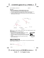
A. WITH A STANDARD AT&T OR GTE MODULAR WALL JACK


1. Install the wall mount bracket at the position as shown in Figure 4. 
2. Connect the short telephone line cord to the TEL LINE jack on rear of the base unit. 
3. Connect the opposite end of the telephone line cord to the modular wall jack.


4.  Align the wall mounting slots with the studs located on the modular wall plate and slide 

the base down to lock in place. 


                                                  Telephone Modular  
                                                                  Wall Jack


  Studs 


                                                                      Wall Mount


               Base Unit          Wall Mounting        Bracket


             (Side View)            Slots


                                                                (Figure 4)


NOTE:

 If you do not have a standard modular wall jack, find a qualified technician to mount 

one on the wall. 

B. WALL MOUNTING (No Standard Wall Jack)


1.  

Drill two holes with a vertical distance between the two marked 
positions of 3 

15/16

” (100 mm) as shown in Figure 5. 

2.  

Drive a screw into each of the holes. Tighten them to the end of the 
screw line, only leaving the smooth part of the screw head outside 
the wall. 

3.  

Hang the unit onto the screws, and then slide it down firmly to


fasten the base securely.                                                                           (Figure 5) 


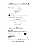
BASE RETAINER TAB 

If the base unit is to be placed in the wall mount position, the base retainer tab allows the 
handset to hang onto the base unit. 


Retainer Tab 


Summary of Contents for gx2400

Page 1: ...on GX2400 Congratulations on your selection of the GX2400 from Audiovox This quality 2 4GHz cordless telephone like all Audiovox products has been designed to give you many years of continuous service...

Page 2: ...ween 9 00a m 5 00p m Eastern Standard Time Mon Fri You can also visit our web site at http www audiovox com for technical support and information on our other products WARNING To prevent fire or shock...

Page 3: ...less proper ventilation is provided 7 This product should be operated only from the type of power source indicated on the marking label If you are not sure of the type of power supply to your home con...

Page 4: ...RBRC is a trademark of Rechargeable Battery Recycling Corporation SAVE THESE INSTRUCTIONS BATTERY SAFETY INSTRUCTION CAUTION To reduce the risk of fire or injury to persons read and follow these inst...

Page 5: ...his equipment does cause harmful interference to radio or television reception which can be determined by turning the equipment on and off the user is encouraged to try and correct the interference by...

Page 6: ...connections themselves but should contact the appropriate electrical inspections authority or electrician as appropriate Your GX2400 is designed to operate at the maximum power allowed by the FCC and...

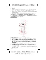
Page 7: ...DESCRIPTION CONTROLS LOCATION AND FUNCTION 16 15 1 14 2 3 13 4 5 6 12 7 11 8 10 9 Figure 1 HANDSET CONTROLS 1 RING OFF LED Indicator Lights when ringer off mode is set 2 TALK Button Press to answer an...

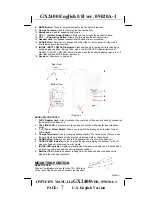
Page 8: ...iew 8 1 2 Bottom View 7 6 5 3 4 Figure 2 BASE UNIT CONTROLS 1 9VDC Adapter Jack A jack located on the rear side of the base unit used for connecting the adapter to the base unit 2 TEL LINE JACK Accept...

Page 9: ...elephone Modular Wall Jack Studs Wall Mount Base Unit Wall Mounting Bracket Side View Slots Figure 4 NOTE If you do not have a standard modular wall jack find a qualified technician to mount one on th...

Page 10: ...receiver and microphone are disabled when the headset is connected Headset Jack Headset Plug 2 5mm Figure 8 Press the TALK button to answer or place a call using the headset Refer to the manufacturer...

Page 11: ...0 Handset Battery Insert the End of the Compartment Battery Pack Wire RED Wire BLACK Wire Figure 10 3 Insert the Ni Cd battery into the battery compartment of the handset 4 Slide the battery compartme...

Page 12: ...e unit The base IN USE LED indicator will turn off B IF THE HANDSET IS OUT OF THE BASE UNIT 1 When the phone rings press the TALK button on the handset The unit will scan for a clear channel until the...

Page 13: ...led numbers Each four second pause occupies one digit of the available 16 digits per memory location FLASH FUNCTION Used to access custom calling features such as Call Waiting or Three Way Calling pro...

Page 14: ...the handset batteries charged as much as possible Weak handset batteries can limit the range of cordless operation MAXIMIZING BATTERY LIFE Repeated use or recharge of Ni Cd batteries without periodic...

Page 15: ...nt unwanted signals there may be periods when these unwanted signals cause interference If interference occurs frequently it can be minimized or eliminated by lowering the height of your base antenna...

Page 16: ...Move the base unit so that it is centrally located in your residence or office and make sure that the base unit is not located near appliances The handset Ni Cd battery may be weak Recharge the Ni Cd...

Page 17: ...GX2400 English I B ver 09020A 1 09020A 1 16 OWNER S MANUAL GX2400VER 09020A 1 PAGE 16 U S English Version Distributed Exclusively Worldwide by Audiovox GX2400 09020A GX2400 09020A 1 1...

Reviews: