background image

128-8797a

9 of 20

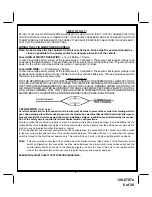
Brake Switch Positive Shutdown Detail

YELLOW w/ BLACK Tracer Wire: 

+ 12 Volt Alarm By - Pass Output

Note: 

You  must disconnect  the  ignition  input  of  the  alarm  from  any  other  wire  that  it  is presently  connected  to

in  the  vehicle.

This wire provides a + 12 Volt output when the ignition key is turned to the “ON” position, and 0 Volts when the ignition
key is “OFF” and when the vehicle is running under the control of the remote starter.
This wire should be connected to the ignition input of the alarm system.
The Yellow w/ Black wire output will allow you to remote start the vehicle while leaving the alarm armed, and to lock/
unlock the doors while running under control of the remote start unit.

(2) WHITE Wires: Parking Light Flashe

r

These wires are the COMMON and NORMALLY OPEN contacts of the on-board parking lamp relay.
If the vehicle's parking lights are a +12 volt switched system, connect (1) of the White wires to a fused (15A max.) +12
volt battery source, and connect the second White wire to the vehicle's parking light wire.
If the vehicle's parking lights are a chassis ground switched system, connect (1) of the White wires to a chassis ground
source, and connect the second White wire to the vehicle's parking light wire.

LIGHT BLUE Wire: 

Ignition 3 / Shock Disable Output

This wire provides a 300mA ground output that becomes active 3 seconds before the Remote Start Unit initializes, and
remains grounded while running plus an additional 4 seconds after the Remote Start Unit turns off. In all of the
applications described below, a relay will be required. The Light Blue wire can be used to accommodate the following
situations:

9

Switch

Summary of Contents for Prestige Platinum APS-57C

Page 1: ...ble Features Bank 2 Is Alarm Selectable Features Feature Selection 1 Chirp 2 Chirps 3 Chirps 4 Chirps 5 Chirps 6 Chirps 1st DoorL UL 1 Sec 3 5 Sec 1 Sec L Dbl U L Dbl L 1 Sec UL Dbl L Dbl UL 1 S l 350...

Page 2: ...th Press and release the valet switch Non Functional On This Unit or Sixth Press and release the valet switch Non Functional On This Unit or Seventh Press and release the valet switch Non Functional O...

Page 3: ...ngine must be started 4 times with the key to be effective 15th R S Shock NA 16th Turbo Select NA 17th Black Blue Aux O P Single Pulse As Feat 1 Bank 2 18th One or Two Press Start Two Press One Press...

Page 4: ...tional On This Unit or Ninth Press and release the valet switch 1 chirp diagnostics off Press transmitter Buttonto change 2 chirps diagnostics on or Tenth Press and release the valet switch 2 chirps c...

Page 5: ...ommand to start is issued This switch must be installed in all applications Failure to do so may result in personal injury or property damage Mount the switch in a location away from water drain paths...

Page 6: ...EXCEEDS 24 AMPS CONTINU OUS WE RECOMMEND THAT TWO FUSES BE USED IN COMBINATION ON EACH POWER WIRE AS SHOWN BELOW FORADDITIONALINFORMATION SEETECH UPDATE ISSUED 9 30 96 YELLOW WIRE Starter Output Care...

Page 7: ...on 2 Output Connect this wire to the ignition 2 wire from the ignition switch This wire will show 12 volts when the ignition key is turned to the ON or RUN position and is some cases the START or CRAN...

Page 8: ...ceived from the transmitter If the brake light switch in the vehicle switches ground to the brake light circuit connect the Gray w Black trace wire to the output of the brake light switch If the brake...

Page 9: ...ng Light Flasher These wires are the COMMON and NORMALLY OPEN contacts of the on board parking lamp relay If the vehicle s parking lights are a 12 volt switched system connect 1 of the White wires to...

Page 10: ...es are typically White w Black trace and Violet w Yellow trace however in later model Cadillacs they are run through an orange sleeve and are either both Black both Yellow or both White wires Consult...

Page 11: ...o unlock the doors Black w Light Green Trace Wire Pulsed Ground Output After Start The Black w Light Green Trace wire will provide a 1 second 300mA pulsed ground output after the vehicle is started un...

Page 12: ...wire of the two pin harness provides a 12 volt pulse during the disarming sequence or pulsed 12 volt unock output Connect the Red wire to the low current 12 volt signal wire from the factory door unl...

Page 13: ...ure number 9 is set to the Diagnostics On mode 2 Press and hold the program switch on then turn the ignition key to the ON position 3 The lights will flash and the number of flashes will indicate the...

Page 14: ...tion 1 With the system disarmed unlocked and the ignition switch off Press and Hold the pushbutton switch located on the receiver unit on 2 Turn the ignition switch on off on off on off 3 The LED begi...

Page 15: ...quires the additional connection of a safety wire from the remote start device to the vehicle Park Neutral ECM Input or the vehicle key in sensor This connection will prevent remote start operation if...

Page 16: ...Audiovox Remote Start Unit F Connect terminal 86 of the relay to a fused 12 volt constant battery source G Connect terminal 87 of the relay to the Chime Module side of the previously cut wire in step...

Page 17: ...ST shown in this manual 2 Pin Transponder Control Output Yellow Connector This output is intended to allow the control of a transponder bypass interface module or transponder bypass relay The system a...

Page 18: ...e engine compartment areas CAUTION Particularly avoid the area around the steering shaft and column as wires can wrap around these mechanisms and impair the safe operation of the vehicle 3 Apply the C...

Page 19: ...128 8797a 19 of 20 19...

Page 20: ...128 8797a 20 of 20 2011 Audiovox Electronics Corp Hauppauge NY 11788 128 8797a This page intentionally left blank For technical support go to www prestigecarsecurity com or call 1 800 225 6074...

Reviews: