background image

10

NOTE:

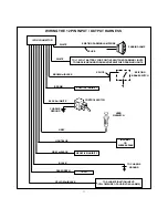
A second 4002 series diode may be required to maintain the integrity of the hood open, shut down
circuit. If this is the case, it must be installed as shown in the diagram above. The anode (Non Striped)
side must be connected to the Gray/Black wire of the Remote Start Unit. The cathode (Striped) side
must be connected to the hood pin switch. If the hood pin switch is also used for an alarm trigger input,
be certain to use a dual diode assembly as shown in the diagram above

.

AFTER THE CONNECTION OF THE NEUTRAL START SAFETY WIRE AS INDICATED IN ANY OF THE
PREVIOUS ALTERNATE CONFIGURATIONS, THIS CIRCUIT MUST BE TESTED FOR OPERATION.
Retest by following the steps outlined in the NEUTRAL START SAFETY TEST shown in this manual.

COMPLETING THE INSTALLATION:

1. Select a desired mounting location for the program switch and the control switch. The switches may be

mounted in or below the dash by drilling a 1/4" dia. hole. Be sure to check behind the dash for adequate

clearance for the body of the switch, and to confirm that the drill will not damage any existing components
as it passes through the dash. Always try to mount these switches so that when the switch is moved to
the upward position it is on (closed to ground). Always place the red switch handle cover, (provided), on the
control switch so it will be easy for your customer to distinguish the control switch from the program switch.

2. Mount the control module behind the dash using cable ties or sheet metal screws.
3. Securely tape and tie all wiring up and away from all hot or moving objects that may come in contact with

under the dash area.

CAUTION:

Particularly avoid the area around the steering shaft and steering column, as wires can wrap around
these mechanisms and impede the vehicles ability to be properly controlled.

4. Apply the Caution label included in the kit to an area in the engine compartment that is clearly visible when

the hood is opened. Make sure the surface is clean before applying the label.

5. Replace all panels that were removed during installation, and re-test the system.
6. Explain all activated features of the remote starter to the customer.

Summary of Contents for Pursuit PRO 9171FT

Page 1: ...ly Model PRO 9171FT Installation Manual KITCONTENTS 1 Remote Start Control Module 2 3 Button RF Keychain Transmitters 2 Wiring Harnesses 1 Parts Bag Containing 2 Fuses 2 Fuse Holders 1 ControlSwitch 1...

Page 2: ...o the vehicle battery always fuse these wires at the source using the 30 A fuses provided The Battery 2 source provides 12 volts to the PRO 9171FT module for Starter output and Accessory output YELLOW...

Page 3: ...to the hood pin switch provided This wire will be routed through the fire wall into the engine compartment It is necessary to use an existing grommet when passing wires through the fire wall to preve...

Page 4: ...ide of the cut wire to terminal 87a of the relay Just before the remote starter is activated the relay contacts will open and the shock sensor will not trigger the alarm Four seconds after the remote...

Page 5: ...the AUDIOVOX Door Lock Wiring Supplement for proper connection to these types of circuits 2 Pin Blue Connector Programming Switch Route the grey and black wires in the 2 pin connector from the program...

Page 6: ...F ON then OFF 4 Immediately turn the ignition key OFF 5 Flip the program switch ON then start the vehicle using the ignition key 6 When the unit senses the tach signal the parking lights will begin to...

Page 7: ...TILYOU CONFIRM THE OPERATION OF THE NEUTRAL SAFETY START FEATURE MECHANICAL NEUTRALSAFETY SWITCH CONSIDERATIONS Mechanical neutral safety switch configurations differ slightly in that they do not offe...

Page 8: ...ditional information concerning Key In Sensor methods 1 2 are listed below and should be reviewed before considering either alternative Method 1 will allow the safety required for the remote start uni...

Page 9: ...to the Drivers Door side of the pin switch wire previously cut in step B NOTE A second 4002 series diode may be required to maintain the integrity of the hood open shut down circuit If this is the ca...

Page 10: ...e clearance for the body of the switch and to confirm that the drill will not damage any existing components as it passes through the dash Always try to mount these switches so that when the switch is...

Page 11: ...1 NEGATIVEINHIBIT2 TACH SPLICE EXISTING BRAKESWITCH IGNITION3 O R SHOCKBY PASS TO CHASSIS GROUND EXISTING PARKING LAMP WIRE SPLICE PARKING LAMP BROWN w BLACK BROWN BLACK w WHITE CHASSIS GROUND GREY w...

Page 12: ...1998 Audiovox Corporation Hauppauge NY 11788 128 5404...

Reviews: