background image

6

PLUG-IN CONNECTIONS AND COMPLETING THE INSTALLATION:

Now that all the other components have been installed, and most of the main connections completed, it is

time to finish connecting the remaining plug-in components and completing the installation. Even though

these are plug-in connections, and the plugs have been shaped such that they cannot be plugged in wrong,

please read and follow the instructions below for each connection to make certain each component is

properly installed.

DASH MOUNTED LED

2-PIN White Plug w/2 Wires; Red & Blue

The Red & Blue wires in the 2-PIN mini white connector control the anode and cathode of the dash

mounted LED. Route the twin lead Red and Blue wires from the LED to the control unit and plug the two pin

connector into the mating white mini connector shell of the control module. Do not force the connector, it

will only plug in one way.

OPTIONAL SHOCK SENSOR
4-PIN White Plug w/4 Wires; Red, Black, Blue, & Green

The Red (+12 volt), Black (ground), Blue (pre-detect) and Green (full trigger when armed) wires loaded
into the white connector shell are the inputs/outputs of the shock sensor. Route the 4 wire harness from
the shock sensor location to the PRO 9842 Control Module and plug the 4-PIN white connector into the
mating 4-PIN connector.

VALET/PROGRAM/MANUAL OVERRIDE SWITCH
2-PIN Blue Plug w/2 Wires; Black & Gray

The Black & Gray wires in the 2-PIN blue connector are the ground supply and Valet/Program input of the
PRO 9842 unit. When the Gray wire is grounded, under certain conditions, the unit will enter the valet
mode. When the Gray wire is sequentially grounded under other conditions, the unit will enter the various
program modes. Route the Black and Grey wires from the Valet/Program/Manual Override switch to the
PRO 9842 unit and plug the blue 2-PIN connector into the mating blue connector shell of the PRO 9842
control module. Do not force the connector, it will only plug in one way. Note: Please refer to the section;
"Programming System Features" shown later in this installation guide to learn the operation of the valet/
program/manual override switch.

POWER DOOR LOCK HARNESS
2-PIN White Plug w/2 Wires; Red & Green

The connection of the power door lock/unlock wires has already been explained. Route the Red and Green
wires to the PRO 9842 unit and plug the white 2-PIN connector into the mating white two pin connector
shell of the PRO 9842 control module. Do not force the connector, it will only plug in one way.

TRANSMITTER PROGRAMMING:

The transmitters supplied with the PRO 9842 are pre-programmed at the factory to provide the following function:

Button 1, pressed and released quickly

=

Arm/Disarm (Lock & Unlock) w/Siren Chirps

Button 1, pressed for ~ 1 second

=

Arm/Disarm (Lock & Unlock) w/o Siren Chirps

Button 1, pressed for ~ 3 seconds

=

Engage/Disengage Panic Mode

Button 2, pressed for ~ 3 seconds

=

Channel 2 Output

If you desire to have the transmitters operate differently from this factory configuration, please refer to the
separate Transmitter Programming Guide that came with the PRO 9842 system.

PROGRAMMING FEATURES:

There are five (5) Programmable Features on the PRO 9842 system. Study the list below, keeping in mind
the features and their defaults, (how it comes programmed from the factory), and decide how best to
program the PRO 9842 for your particular installation.

Summary of Contents for Pursuit PRO 9842

Page 1: ...s With 12 Volt Negative Ground Electrical Systems Only Kit Contents PRO 9842 Control Module 2 Two Button Transmitters 2 Channel Code Learning Receiver 1 Multi Pin Input Output Harness 1 Two Pin Door Lock Harness 1 Two Pin LED Indicator 1 Two Pin Valet Programming Switch Multi tone Siren 1 Installation Manual 1 Operator s Manual 1 Limited Warranty 2 Window Decals ...

Page 2: ...artment for maximum sound distribution Before securing the siren check behind your chosen location to assure that the mounting screws will not penetrate any factory wiring or fluid lines Secure the siren mounting bracket using 8 self taping screws by first using the mounting bracket as a template scribe or mark the three bracket mounting holes Drill the three marked holes using a 1 8 drill bit tha...

Page 3: ...harness These fuseholders each hold a separateATC fuse one 5AMP and one 15AMP This RED wire must be connected to a constant power wire at the vehicle s ignition switch harness or fusebox Most vehicles have at least one battery source wire supplying power to the ignition switch Locate a constant power wire or power taping point either at the vehicle s ignition switch harness or fuseblock This wire ...

Page 4: ...use any of the diodes in this series with the 1N4003 and 1N4007 being the most common types The diodes must be installed with careful regard for their direction of current flow Note This wire will be shunted when remote control channel 2 is accessed trunk release This wire will remain shunted all the while there is ground present and for 5 seconds after the ground is removed This allows the operat...

Page 5: ...k circuit of the vehicle you are working on and wire according to the diagrams shown WIRING FOR GROUND PULSE DOOR LOCK CIRCUITS This is a system commonly used on most import vehicle s factory door lock unlock systems and with a few domestic vehicles which employ factory keyless entry systems In this application the Red wire serves as the Lock output providing a ground pulse during the arming seque...

Page 6: ...et mode When the Gray wire is sequentially grounded under other conditions the unit will enter the various program modes Route the Black and Grey wires from the Valet Program Manual Override switch to the PRO 9842 unit and plug the blue 2 PIN connector into the mating blue connector shell of the PRO 9842 control module Do not force the connector it will only plug in one way Note Please refer to th...

Page 7: ...tant to note that when you first enter the Programming Mode you are automatically positioned to adjust the First Programmable Feature and that the Valet Program Manual Override Switch allows you to toggle from there through each of the four more programmable features However it will not allow you to return to any feature once you have toggled past it Should you accidentally toggle past the feature...

Page 8: ...location will not inhibit any of the controls of the vehicle 2 Securely harness and tie all wiring up and away from all hot and moving parts that they may come in contact with under the dash board or in the engine compartment areas CAUTION Particularly avoid the area around the steering shaft and column as wires can wrap around these mechanisms and impair the safe operation of the vehicle 3 Check ...

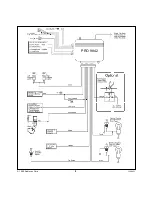
Page 9: ...9 1999 Audiovox Corp 128 5451 PRO 9842 To Optional Plug In Shock Sensor ...

Reviews: