background image


6


8


7


5


4


3


2


1


14

17

15

16

9

10

11

12

13

MUTE

P4

P3

P2

P1

VOLUME

SEEK


CH

19

12:00

18

DEL

ADD

SET

AM

FM

TV

AP

 19

ON/OFF

7) 

Insert the rubber pieces (#6) (Foot, Mounting Cap - please refer to the illustration above) into 

the unit.    Install the blank cover on the unused port. 


1)  

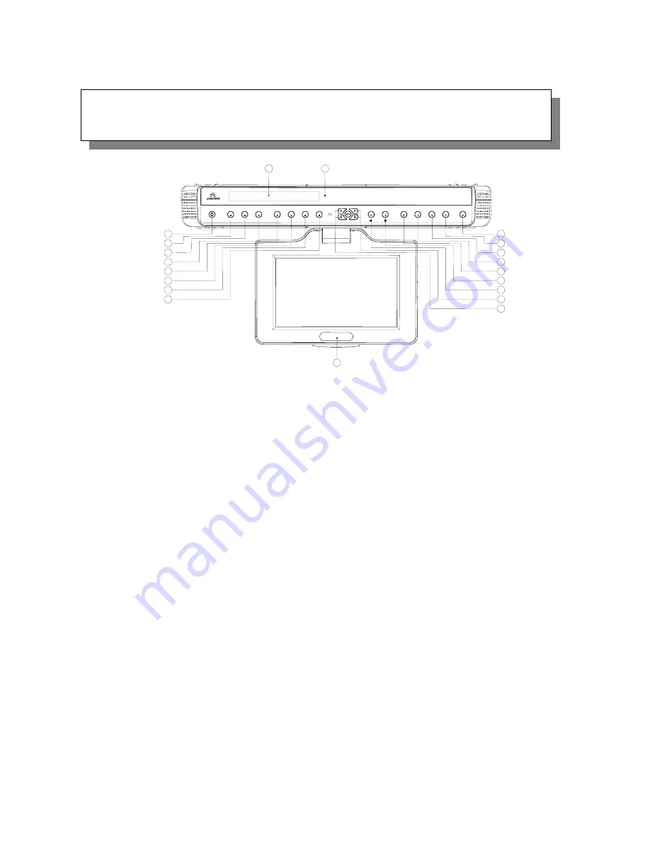
ON/OFF BUTTON –

 Power ON/OFF. 

2)  

SET BUTTON –

 Press this button to set the

ALARM, TV Mode or Speaker Mode. 

n to start the Auto Program feature. 

Hold this button to change 

8)  

9) 


o mute the audio (++++ will appear and blink on the 


11)  

12)  

ed Preset Channel “2” in the Radio or TV mode. 

14) 


utton to raise the volume. 


16)  

uttons to go to next available channel with 

sufficient signal 

17) 

  CHANNEL BUT

 next available channel. 

18)  

DISPLAY WINDOW –

 Displays the channel/station number, time, and selected source. 

19) 

  REMOTE INFRARED SENSORS-

These sensors receive infrared command signals from the 

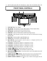
FRONT PANEL CONTROLS


TIME, 

3) 

    ADD BUTTON – 

Press this button to add a selected channel. 

4)  

DEL BUTTON –

 Press this button to delete a selected channel. 

5) 

    AP BUTTON –

 Press and Hold this butto

6)  

TV BUTTON –

 Press this button to select TV mode and Press and 

the aspect ratio.   

7) 

  FM BUTTON –

 Press this button to select FM Radio mode. 

AM BUTTON –

 Press this button to select AM Radio mode. 

MUTE BUTTON –

 Press this button t

display when the system is muted). 

10) 

P4 - BUTTON –

 Selected Preset Channel “4” in the Radio or TV mode 

P3 - BUTTON –

 Selected Preset Channel “3” in the Radio or TV mode. 

P2 - BUTTON –

 Select

13)  

P1- BUTTON –

 Selected Preset Channel “1” in the Radio or TV mode. 

VOLUME UP (

X

) BUTTON –

 Press this b

15) 

VOLUME DOWN (

W

) BUTTON –

 Press this button to lower the volume. 

SEEK BUTTONS (

TS

-Right Side) –

 Press these b

strength. 

TONS (

TS

-Left Side) –

 Press these buttons to go to

    - 

10

Summary of Contents for VE705 - VE - 705

Page 1: ...0 Multi function Remote Control Cable Ready 125 Channel TV Tuner Internal Stereo Speakers Under Cabinet Table Top Mounting AM FM Radio Tuner...

Page 2: ...e presence of uninsured dangerous voltage within the product s enclosure that may be of sufficient magnitude to constitute a risk of electric shock to persons This symbol is intended to alert the user...

Page 3: ...erence to radio or television reception which can be determined by turning the equipment off and on the user is encouraged to try to correct the interference by one or more of the following measures R...

Page 4: ...t Any mounting of the product should follow the manufacture s instructions and should use the mounting accessories recommended by the manufacturer 9 Carts A product and cart combination should be move...

Page 5: ...utside antenna system extreme care should be taken to keep from touching such power lines or circuits as contact with them might be fatal 17 Overloading Do not overload wall outlets extension cords or...

Page 6: ...cted in this manual 24 Heat The product should be situated away from heat sources such a radiators heat registers stoves or other products including amplifiers that produce heat Cable System Installat...

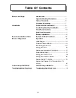
Page 7: ...esktop Installation 9 Front Panel Controls 10 Rear Panel Controls 11 Battery Installation 12 Remote Control Functions 13 Operation 14 Initial Set up 14 Channel Tuning Set up 14 Positioning the Screen...

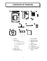
Page 8: ...Mounting Hole Template 11 Owners Installation Manual 1 VE705 TV 2 Hardware bag A 3 4 Mounting screws 4 B 1 1 4 Mounting screws 4 C 1 1 2 Mounting screws 4 D Foot 4 E Hole cap 4 3 Remote Control 4 Mult...

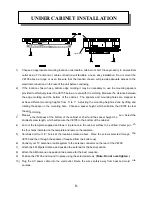
Page 9: ...he ure sources 1 e mounting lo r shelf Close proxim nna or cable con at easy installation Do not mou range or oven Be su n wi l provide adequate acce 2 ti UNDER CABINET INSTALLATION Edge Molding e mol...

Page 10: ...2 Remove the connector from the unit 3 be careful not to damage the screen 5 4 Turn the unit over and remove the blank cover 4 5 Connect the plug of the LCD monitor into the connector 3 Note align th...

Page 11: ...lected source 19 REMOTE INFRARED SENSORS These sensors receive infrared command signals from the FRONT PANEL CONTROLS TIME 3 ADD BUTTON Press this button to add a selected channel 4 DEL BUTTON Press t...

Page 12: ...NE CORD Connects to AC power outlet 2 FM ANTENNA Allows the VE705 to be connected to a 75 Ohm the reception of FM broadcast signals 3 AM ANTENNA Allows the VE705 to be connected to an external antenna...

Page 13: ...l face down Place a fingernail or coin in the open slot slide battery holder out 2 Install the CR2025 battery into its proper slot Note Be sure to observe the correct polarity when inserting the batte...

Page 14: ...d the VE705 will alternate between AM and FM 8 TV BUTTON TV Used to select TV function Press and Hold to change the TV aspect ratio 9 MUTE BUTTON MUTE Press this button to mute the audio will blink on...

Page 15: ...hannel search mode is conclu POSIT Press the screen lock button and pivot the screen forward until a comfortable viewing angle is reached The sc he screen beyond its rotational limit The VE705 is now...

Page 16: ...n setting the alarm check the AM PM indicator to assure th 4 Press the Power butto sound each day at the same time as long as it is activated DEACTIVATING ALARM 1 Press the SET button twice to enter t...

Page 17: ...TV Cable configuration mode 2 Press the SEEK button to select the AIR mode Press the POWER button to confi TING THE PRESETS IN AM FM OR TV MODES Tune the desired channel station 2 Press the SET butto...

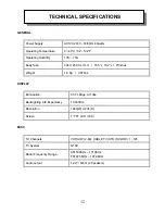
Page 18: ...4 X 259 X 47mm 15 5 x 10 2 x 1 9 Inches Weight 1 8 Kg 3 97Lbs DISPLAY Illumination CCFL Edge Lit Tube Backlighting Life Expectancy 10 000Hrs Resolution 1440 W X 234 H Screen 7 TFT LCD 16 9 MISC TV Cha...

Page 19: ...Verify that the sensor on the VE705 is not erify that the infrared LED on the transmitter is not obstructed Check the condition of the remote control obstructed V batteries Black and White Reception V...

Page 20: ...19 128 7325...

Reviews: