background image


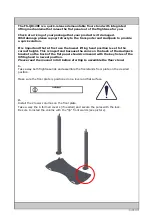
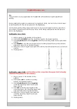
FS-QR120E version only


9a.


This procedure is only applicable for FS-QR120E with electronic height adjustment 
setting. 
 
 
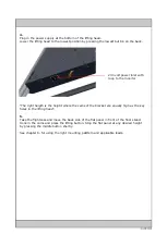
During testing the system is aready set to maximum limits, but not to the correct lower 
screen height (with the screen placed in the flightcase).  
 
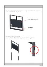
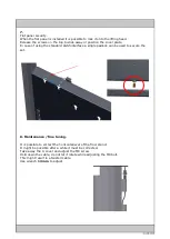
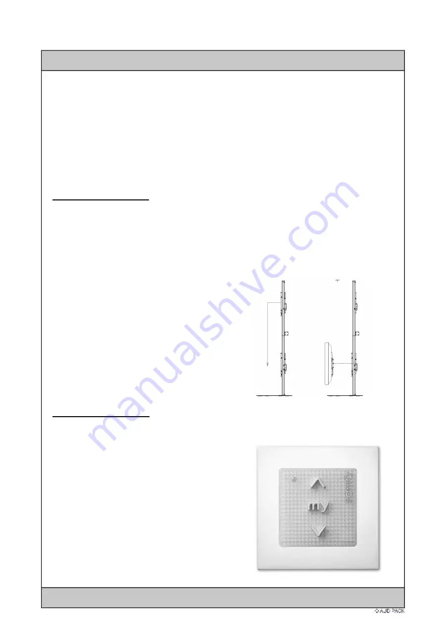
For the first use the lifting head must be set in the correct height to let the cams from 
the monitor bracket insert into the key holes of the lifting head (while the flat panel is 
still in the flightcase). 
 

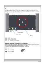
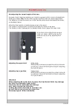
Setting the lower limit. 


1.


Plug in power in the bottom of the system. 

2.


Push button 

DOWN

 to set the mounting head to the lowest position 

3.


Pusch 

Up & Down

 buttons 

together

 untill the mounting head moves up & down 

shortly 

4.


Push 

DOWN

 to set the new height of the mounting head; the key-holes should 

align with cams of the monitor bracket. 

5.


When the correct height is set push MY until the mounting head moves up & down 

shortly. 

6.


Unplug power. 


Setting the upper limit 

(perform this action only when the upper limit is faulty; 

standard this postion is set already).


1.


Plug in power in the bottom of the 

system. 

2.


Push button 

UP

 to set the mounting 

head to the highest position 

3.


Pusch 

Up & Down

 buttons 

together


untill the mounting head moves up & 
down shortly 

4.


Push 

UP

 to set the new height of the 

mounting head; the mounting head must 
stop just before the mechanical limit. 

5.


When the correct height is set push MY 

until the mounting head moves up & 
down shortly. 

6.


Unplug power. 


Summary of Contents for FS-QR120E

Page 1: ...Mounting and manual instruction FS QR120E FS QR160E floor stand Copyright Audipack ...

Page 2: ...his is importand because the cams on the back of the Audipack bracket on the back of the flat panel should corresond with the key holes of the llifitng head in lowest position Please read the manual in full before starting to assemble the floor stand 1 Take away both flightcase lids and assemble the floorstands floor plate on the desired position Make sure the floor plate is positioned on a level ...

Page 3: ...the side of the colums Do not lift at the lifting head Do not lift the lifting head Grip handle Make sure both pins slide in equally At uncontrolled placing it might be more difficult to connect the coloumns Also lock this assembly with the locks tip lock afther full completion ...

Page 4: ...right heigth is the height where the cams of the bracket are equally high as the key holes in the lifting head 5 Take the flightcase and move the back side of the flat panel in front of the floor stand Hook in the cams and press the lifting button Stop the flat panel at any desired height by pressing the middle button shortly See chapter 6 for using the right mounting patttern and applicable loads...

Page 5: ... VESA 600 L S5 Applicable loads VESA 400 max load 120 Kg VESA 600 max load 120 Kg L S5 max load 85 Kg with UFPRO Flat panel installation with VESA interface and cams When the flat panel is equipped with a VESA interface according the example the screen can be installed with the cams inserted directly in the back Choose one of the below optional cams to insert in the back M6 part no 392618 M8 part ...

Page 6: ... standard L S5 interface a single padlock can be used to secure the set 8 Maintanance fine tuning It is possible to correct the horizontallevel of the floor stand It might be possible after a while it must be corrected Take away the C cover and udjust the M8 screw Hold down the cable do not let it rotate while adjusting the M8 bolt This might result in a twisted cable Use wrench 13 mm to adjust ...

Page 7: ... Down buttons together untill the mounting head moves up down shortly 4 Push DOWN to set the new height of the mounting head the key holes should align with cams of the monitor bracket 5 When the correct height is set push MY until the mounting head moves up down shortly 6 Unplug power Setting the upper limit perform this action only when the upper limit is faulty standard this postion is set alre...

Page 8: ...front of the lifting head coloured knobs are visible With an alan key the positions can be set by adjusting their position Adjusting the upper limit White knob While giving command up adjust the white knob with an alan key Check left and right turning for adjusting the right direction Adjusting lower position Yellow knob While giving command up adjust the yellow knob with an alan key Check left an...

Page 9: ...x Motor running time 4 minuten 9 minuten cool down period FS QR160E Maximale load 85 Kg with L S5 mounting interface 160 Kg with VESA 400 and 600 interface with cams Power supply 230 VAC 50 60 Hz Max Motor running time 4 minuten 9 minuten cool down period For questions or service please contact Audipack Industriestraat 2 2751 GT Moerkapelle 31 0 79 593 1671 ...

Reviews: