General information
17
13
General information
13.1
Definitions
- Move motor to zero or reference point (counter)
Twin mode - Parallel or synchronous mode for 2 separate drive units
13.2
End switches
End switches, also called limit switches restrict the movement of the motor in
both directions.
The limit switches are related to the rotation direction of the motor.
It is important to connect the motor so that the direction of motion corresponds
to the controls and limit switches.
In any case the movement stops on both switches, but when the motion
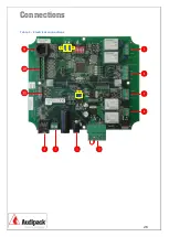
direction and limit switch do not match, the two led’s (U2 and U3) of the
corresponding limit switches on the PCB start blinking.
13.3
Memory positions and directions
The memory positions M1 to M4 must be set in a specific order in between the
two limit switches. They differ of the selected program and are also related to the
buttons of the remote control.
Program “0” and “4”
M1
correspond with the left/down direction
M2
correspond with the right/up direction
M3
is not assigned
M4
is not assigned
Program “1”
M1
correspond with the left/down memory position between
M3
and
M4
, and
down position of the RC (free programmable)
M2
correspond with the right/up memory position between
M3
and
M4
, and up
position of the RC (free programmable)
M3
lowest memory position, close to limit switch down (factory setting)
M4
upper memory position, close to limit switch up (factory setting)
Program “2”, “3” and “5”
M1
correspond with down position of the RC (free programmable)
M2
correspond with the up position of the RC (free programmable)
M3
memory position is free programmable
M4
memory position is free programmable


