-
installer
GIALIX 24 MA C -BC
manual
-
-
installer
GIALIX 24 MA C -BC
manual
-
15
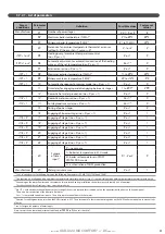
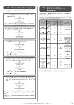
3.6.5 - Connection to the control circuit
1 - 2
: Ambient temperature
thermostat or sensor
(TA or SA)
3 - 4
: Exterior sensor
5 - 6
: Domestic hot water sensor
or DHW aquastat
8 - 10 : 230V power supply of the
DHW 3-way valve with
counter spring (motor
supplied in case of DHW
request)
10 - 11 : Total load shedding DT
(remove the jumper) and/or
the underfloor heating 65°C
temperatue limiter with
manual reset (mandatory)
(see § «Description»)
12 - 13 : Partial load shedding DP1
(remove the yellow jumper)
4 - 15 : Partial load shedding DP2
(remove the yellow jumper)
20 - 21 : Timer
• To prevent disturbances in sensor
readings by the regulator,
independently wire the cables for the
electrical network (raceways, cable
channels), and avoid junction boxes.
• The conductors must be made of electrolytic
copper (no oxidization of the stripped sections
of cable).
• The use of telephone wire is forbidden (multiple
strands lead to weaker cable sections and
broken connections).
• The width of cable sections must be between
0.5 and 2.51mm².


