38
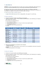
Appendix: Installation control datasheet (to be filled in after starting the installation)
Installed by:
Installer’s name: ___________________________________________
Company name:_________________________________________
Address:__________________________________________
Telephone: ________________________________________
Installation date: ___/___/___
CONFIGURATION PARAMETERS:
1
HRglobal model
2
Working mode
CA LS CPs TQ Other
3
If CA mode:
m³h K1 =
m³h K2 =
m³h K3 =
4
If TQ mode:
%TQ K1 =
%TQ K2 =
%TQ K3 =
5
If LS mode:
Vmin =
Vmax =
m³h (or %TQ)
≡
Vmin =
m³h (or %TQ)
≡
Vmax =
% on K3 =
6
If CPs mode:
Assignment Pa= V (or Pa)
% on K3 =
7
% EXH/SUP
%
8
Pressure alarm (modes CA / LS only)
Activated? yes / no
If yes:
Automatic / Manual setup
Initialisation:
Supply: m³h
Pa
Exhaust: m³h
Pa
9
If KWin option :
T° KWin = °C
10
If KWout option
T° KWout = °C
11
If NV option :
T° NV
= °C
Indicate here all changes made in the advanced setup, if any:
VALUES READ OFF DISPLAY WHEN HRg in OPERATION:
1
Supply Airflow (or torque) 1
m³/h (or %TQ)
2
Supply pressure 1
Pa
3
Supply airflow (or torque) 2 (HRg 4000/5000/6000 only)
m³/h (or %TQ)
4
Supply pressure 2 (HRg 4000/5000/6000 only)
Pa
5
Exhaust airflow (or torque) 1
m³/h (or %TQ)
6
Exhaust pressure 1
Pa
7
Exhaust airflow (or torque) 2 (HRg 4000/5000/6000 only)
m³/h (or %TQ)
8
Exhaust pressure 2 (HRg 4000/5000/6000 only)
Pa

