background image


46


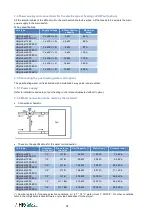
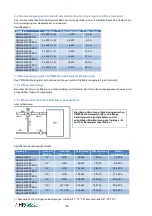
3.4 Stromversorgung und Anschluß des elektrischen Nachheizregisters KWout (optional) 


Alle internen Kabel des Nachheizregisters KWout zum Hauptschalter sind vorverdrahtet. Bauseits ist lediglich die 
Stromversorgung zum Hauptschalter zu realisieren. 


Spezifikationen: 


Gerätetyp 

Spannung 

KWout Heizleistung 

Max. Strom 

HRglobal 800 
HRglobal 800 ECO 

3 x 400V + N 

3 kW 

4,3 A 

HRglobal 1200 
HRglobal 1200 ECO 

3 x 400V + N 

4,5 kW 

6,5 A 

HRglobal 2000 
HRglobal 2000 ECO 

3 x 400V + N 

6 kW 

8,7 A 

HRglobal 3000 
HRglobal 3000 ECO 

3 x 400V + N 

9 kW 

13,0 A 

HRglobal 4000 
HRglobal 4000 ECO 

3 x 400V + N 

12 kW 

17,3 A 

HRglobal 5000 
HRglobal 5000 ECO 

3 x 400V + N 

18 kW 

26,0 A 

HRglobal 6000 
HRglobal 6000 ECO 

3 x 400V + N 

18 kW 

26,0 A 


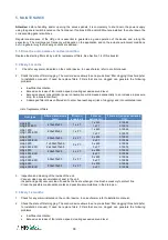
3.5 Stromversorgung für das PWW-Nachheizregister NV (optional) 


Das PWW-Nachheizregister wird mit einem 3-Wege-Ventil mit Stellmotor ausgeliefert (nicht montiert).  
 

3.5.1 Stromversorgung: 


Beachten Sie bei der Installation und der Einstellung der Parameter die im Handbuch angegebenen Hinweise (wird 
bei gewählter Option NV mitgeliefert). 


3.5.2 Wasseranschluß (vom Installateur auszuführen): 


Anschlußschema: 


Spezifikation der Wasseranschlüsse: 
 

Gerätetyp 

Anschluß 

Register 

Anschluß  

3-Wege-Ventil 

Heizleistung 

(*) 

Wassermenge 

(*) 

Wasser-

Druckverlust (*) 

HRglobal 800 
HRglobal 800 ECO 

1/2’’ 

G 1B 

4,5 kW 

199 l/h 

1,4 kPa 

HRglobal 1200 
HRglobal 1200 ECO 

1/2’’ 

G 1B 

8,0 kW 

353 l/h 

6,5 kPa 

HRglobal 2000 
HRglobal 2000 ECO 

1/2’’ 

G 1B 

13,2 kW 

585 l/h 

20,4 kPa 

HRglobal 3000 
HRglobal 3000 ECO 

1/2’’ 

G 1B 

 19,4 kW 

857 l/h 

11,1 kPa 

HRglobal 4000 
HRglobal 4000 ECO 

1/2’’ 

G 1B 

 27,8 kW 

1200 l/h 

26,8 kPa 

HRglobal 5000 
HRglobal 5000 ECO 

1/2’’ 

G 1 1/4B 

 37,5 kW 

1657 l/h 

56,9 kPa 

HRglobal 6000 
HRglobal 6000 ECO 

1/2’’ 

G 1 1/4B 

 41,6 kW 

1835 l/h 

68,5 kPa 


(*) Nominelle Werte für folgende Bedingungen: Lufteintritt T°: 18°C, Wasser Ein-/Austritt T: 90/70°C.  

Die interne Verrohrung (Verbindung zwischen 
PWW-Nachheizregister (NV) und 3-Wege-
Ventil ist durch den Installateur vor der 
endgültigen Positionierung des Gerätes z. B. 
an einer Raumwand auszuführen ! 

Summary of Contents for HRg 1200

Page 1: ...KLIMAATTECHNIEK Als het om lucht gaat T 0320 28 61 81 www auerhaan klimaattechniek nl ...

Page 2: ...0 3 1 2 Principeschema voor de T voelers in de ventilatiekast 21 3 2 Aansluiten van de voeding van de ventilatoren en de regeling 21 3 3 Aansluiten van de voeding van de electrische batterij voor antivriesbeveiliging KWin optie 21 3 4 Aansluiten van de voeding van de electrische naverwarmingsbatterij KWout optie 22 3 5 Aansluiten van de warmwaterwisselaar voor naverwarming NV optie 22 3 5 1 Electr...

Page 3: ...n van de 230V voeding Enkele waarden die u moet controleren Voeding 230VAC 210V V 250V Frequentie 50 60 Hz Aarding verplicht De motoren zijn beschermd tegen overspanning Het is dus niet nodig om een electrische beveiliging hiertegen te voorzien Zie 3 2 voor gedetailleerde instructies Isolatieklasse Mechanisch IP44 Nominale temperatuur 10 C 55 C Conformiteit CE en UL gekeurd Opstarten Vooraleer u h...

Page 4: ...7 3 x M5 510092 3 x F7 510074 HRg 4000 HRg 4000 ECO 436x370x50 4 x F7 4 x M5 510093 4 x F7 510056 HRg 5000 HRg 5000 ECO 503x370x50 5 x F7 5 x M5 510094 5 x F7 510058 HRg 6000 HRg 6000 ECO 503x370x50 5 x F7 5 x M5 510094 5 x F7 510058 1 5 Fiche met de instellingen van uw installatie Na het beëindigen van de installatie raden wij u aan om de installatiefiche in bijlage in te vullen Deze fiche bevat ...

Page 5: ...stoten en regeninslag 2 2 Aansluiten van de kondensbak Voor een optimale kondensafvoer raden wij u aan om de luchtbehandelingskast in een hoek van 2 te plaatsen Zo vermijdt u dat er water in de kondensbak zou blijven staan Het aansluiten van de siphon HRg binneninstallatie Controleer alvorens de luchtgroep op te starten dat de aansluitingen tussen de kondensbak de siphon en het afwateringskanaal v...

Page 6: ... siliconen Zie foto a b Plaats de dakplaten op de groep en zorg voor een overhang van 56mm aan de zijkanten en van 105mm aan de pulsie en extractiezijden Zie foto b a b c Steek de schroeven in de beschermkapjes Draai de zelfborende schroeven door het dakpaneel in het aluminium profiel Zie foto c d Spuit siliconen in het profiel dat de verschillende dakpanelen moet samenhouden Zie foto s d1 en d2 c...

Page 7: ...ectrische of warmwater naverwarming optie KWout of NV 7 Gemotoriseerde klep aan de aanzuigzijde van verse lucht optie 8 F7 filter aan de aanzuigzijde van verse lucht 9 Electrische verwarming als antivriesbeveiliging optie KWin 10 Kondensbak en de evacuatieaansluiting 11 By pass 100 12 Lucht lucht warmtewisselaar 13 M5 filter aan de afzuigzijde van gebruikte lucht of F7 in optie 14 Gemotoriseerde k...

Page 8: ... 3 D 10 000A AC3 20A 4 HRglobal 4000 ECO 1 x 230V 13 2 A D 10 000A AC3 16A HRglobal 5000 3 x 400V N 18 0 A 3 D 10 000A AC3 20A 4 HRglobal 5000 ECO 3 x 400V N 5 8 A D 10 000A AC3 8A HRglobal 6000 3 x 400V N 23 1 A 3 D 10 000A AC3 25A 4 HRglobal 6000 ECO 3 x 400V N 5 8 A D 10 000A AC3 8A 1 Aarding VERPLICHT 2 Electrische beveiliging uitschakelkarakteristiek type D kortsluitvermogen 10 000A AC3 3 Max...

Page 9: ...e Deze wisselaar wordt geleverd met een niet gemonteerde 3 wegklep 3 5 1 Electrische aansluitingen Zie de meegeleverde handleiding van de 3 wegklep 3 5 2 Hydraulische aansluitingen te doen door de installateur Aansluitschema Aansluitspecificaties Type kast Aanslui ting NV Aansluiting 3 wegklep Vermogen Waterdebiet Drukverlies HRglobal 800 HRglobal 800 ECO 1 2 G 1B 4 5 kW 199 l h 1 4 kPa HRglobal 1...

Page 10: ... instellen controleren en weergeven van de parameters Voor meer details zie de installatie en gebruikshandleiding TAC5 GRC Optie SAT BA KW Besturing van externe warmtewisselaars electrisch of met warm water Voor meer details zie de installatie en gebruikshandleiding SAT BA KW Optie SAT3 Circuit met 2 relais voor Staat van de ventilatoren en drukalarm weergeven in positie O R 1 O R 2 of Bedienen va...

Page 11: ... Type filters Type kast Afmetingen filters mm Filter Pulsie Filter Extractie Kit Filters pulsie extractie CID HRg 800 HRg 800 ECO 470x287x50 1 x F7 1 x M5 510089 1 x F7 510072 HRg 1200 HRg 1200 ECO 830x287x50 1 x F7 1 x M5 510090 1 x F7 510073 HRg 2000 HRg 2000 ECO 503x370x50 2 x F7 2 x M5 510091 2 x F7 510054 HRg 3000 HRg 3000 ECO 1 x 503x370x50 2 x 436x370x50 3 x F7 3 x M5 510092 3 x F7 510074 H...

Page 12: ...ndens opvegen en de kondensbak schoonmaken De binnenkant van de By pass schoonvegen Om toegang te krijgen tot de binnenkant van de By pass moet u het volgende doen maak een brug tussen de klemmen IN4 en 12V van het TAC5 circuit De By pass zal opengaan ongeacht de gemeten temperatuur Na het onderhoud niet vergeten om deze overbrugging te ontkoppelen 4 Onderhoud van de ventilatoren Vooraleer het ond...

Page 13: ...op K3 7 AF TOE 8 Drukalarm mode CA LS Gebruikt ja neen Indien gebruikt initiële waarden Pulsie m u Pa Extractie m u Pa 9 Indien optie KWin T KWin C 10 Indien optie KWout T KWout C 11 Indien optie NV T NV C Als u in de advanced setup parameters heeft aangepast noteer deze dan hieronder Werkingsparameters 1 Pulsiedebiet of Pulsiekoppel 1 m u of TQ 2 Pulsiedruk 1 Pa 3 Pulsiedebiet of Pulsiekoppel 2 e...

Page 14: ...ormation 32 3 1 1 General schematic of the HRg units 32 3 1 2 Schematic of the T sensors positioning in the HRg units 33 3 2 Power supply to the fans and the control devices 33 3 3 Power supply for the electrical antifreeze protection coil KWin option 33 3 4 Power supply and connections for the electrical post heating coil KWout option 34 3 5 Connecting the post heating water coil option 34 3 5 1 ...

Page 15: ...cal specifications Power supply voltage 230VAC 210V V 250V Power supply frequency 50 60 Hz Grounding the unit is compulsory The motor is self protected against overloading It is thus NOT necessary to install an electrical overload protection device See section 3 2 for detailed wiring instructions Insulation class Fans HRg IP44 Nominal temperatures 10 C 55 C Conformity CE motors are also UL approve...

Page 16: ... 1 x 503x370x50 2 x 436x370x50 3 x F7 3 x M5 510092 3 x F7 510074 HRg 4000 HRg 4000 ECO 436x370x50 4 x F7 4 x M5 510093 4 x F7 510056 HRg 5000 HRg 5000 ECO 503x370x50 5 x F7 5 x M5 510094 5 x F7 510058 HRg 6000 HRg 6000 ECO 503x370x50 5 x F7 5 x M5 510094 5 x F7 510058 1 5 Installation control datasheet see appendix When the installation is completed and running we strongly advise that the install...

Page 17: ...rm winds and rain 2 2 Connecting the drain pan To insure a good flow of the condensates the unit should be slightly inclined 2 in the direction of the water flow This also avoids water stagnation in the drain pan The siphon must be properly installed to allow good water flow If the HRglobal unit is installed indoors Before starting control the following points if the drain pan is watertight the co...

Page 18: ... you leave an adequate distance on each side of the unit so as to cover the whole unit properly Suggested distance 50mm on the sides and 100mm on the front and back of the HRg a b c Use the supplied M8 screws to screw the roof onto the HRg unit The screws must be screwed into the aluminium profile and properly aligned Use a pen to point the location of the screw Mount the plastic caps supplied ove...

Page 19: ...ed 4 Supply fan s 5 Exhaust fan s 6 Post heating water or electrical coil NV or KWout option 7 Motorized damper at fresh air inlet CT option 8 F7 class filter at fresh air inlet 9 Pre heating electrical antifreeze coil KWin option 10 Drain pan and drain 11 Modulating 100 by pass 12 Air Air heat exchanger 13 M5 filter on exhaust air or F7 in option 14 Motorized damper at exhaust air inlet CT option...

Page 20: ...bal 4000 3 x 400V N 18 0 A 3 D 10 000A AC3 20A 4 HRglobal 4000 ECO 1 x 230V 13 2 A D 10 000A AC3 16A HRglobal 5000 3 x 400V N 18 0 A 3 D 10 000A AC3 20A 4 HRglobal 5000 ECO 3 x 400V N 5 8 A D 10 000A AC3 8A HRglobal 6000 3 x 400V N 23 1 A 3 D 10 000A AC3 25A 4 HRglobal 6000 ECO 3 x 400V N 5 8 A D 10 000A AC3 8A 1 Grounding is compulsory 2 D type slow reaction curves shutoff power 10 000A AC3 3 Max...

Page 21: ...ed 3 way valve non mounted 3 5 1 Power supply Refer to installation and setup of post heating control manual delivered with NV option 3 5 2 Water connection to be made by the installer Connection schematic These are the specifications for the water coil connection Unit type Diameter on the coil Diameter on the valve Coil Capacity Water flow Pressure loss HRglobal 800 HRglobal 800 ECO 1 2 G 1B 4 5 ...

Page 22: ...TAC5 RC installation and user s manual for detailed information GRC Option graphic remote touchscreen to setup control and visualize the parameters Please refer to TAC5 GRC installation and user s manual for detailed information SAT BA KW Option Regulation of 2 external heat exchangers electrical water hot and or cold please refer to SAT BA KW installation and user s manual for detailed informatio...

Page 23: ... damaged filter allows unfiltered air to enter heat exchanger risk of clogging and into ventilated room List of replacement filters Unit type Filters dimensions mm Filter on supply air Filter on exhaust air Filters kit supply exhaust CID HRg 800 HRg 800 ECO 470x287x50 1 x F7 1 x M5 510089 1 x F7 510072 HRg 1200 HRg 1200 ECO 830x287x50 1 x F7 1 x M5 510090 1 x F7 510073 HRg 2000 HRg 2000 ECO 503x37...

Page 24: ...ce open it proceed as follows jump terminals IN4 and 12V on the TAC5 circuit board The bypass is now open independently of temperature conditions Remember to remove jump between terminals IN4 and 12V once cleaning of bypass is done 4 Fan maintenance Check again if power supply is shut down and fans are not running Check cleanness of fan Clean if necessary be careful not to alter balancing of the f...

Page 25: ...n m h or TQ Vmax on K3 6 If CPs mode Assignment Pa V or Pa on K3 7 EXH SUP 8 Pressure alarm modes CA LS only Activated yes no If yes Automatic Manual setup Initialisation Supply m h Pa Exhaust m h Pa 9 If KWin option T KWin C 10 If KWout option T KWout C 11 If NV option T NV C Indicate here all changes made in the advanced setup if any VALUES READ OFF DISPLAY WHEN HRg in OPERATION 1 Supply Airflow...

Page 26: ...formationen 44 3 1 1 Allgemeines Schema der HRg Geräte 44 3 1 2 Positionsschema der Temperatursensoren T 45 3 2 Stromversorgung für Ventilatoren und Kontrolleinrichtungen 45 3 3 Stromversorgung für das elektrische Vorheizregister KWin optional 45 3 4 Stromversorgung und Anschluß des elektrischen Nachheizregisters KWout optional 46 3 5 Stromversorgung für das PWW Nachheizregister NV optional 46 3 5...

Page 27: ...elektrischen Spezifikationen Versorgungsspannung 230VAC 210V V 250V Frequenz 50 60 Hz Erdung der Einheit ist zwingend notwendig Der Motor ist gegen Überlast eigensicher Es ist deshalb nicht notwendig einen elektrischen Überlastschutz zu installieren Siehe Abschnitt 3 2 für detaillierte Hinweise Schutzklassen Ventilatoren HRg IP 44 Temperaturbereich 10 C 55 C Konformität CE Vor der Inbetriebnahme d...

Page 28: ... 3 x F7 3 x M5 510092 3 x F7 510074 HRg 4000 HRg 4000 ECO 436x370x50 4 x F7 4 x M5 510093 4 x F7 510056 HRg 5000 HRg 5000 ECO 503x370x50 5 x F7 5 x M5 510094 5 x F7 510058 HRg 6000 HRg 6000 ECO 503x370x50 5 x F7 5 x M5 510094 5 x F7 510058 1 5 Daten Kontrollblatt für Inbetriebnahme siehe Anhang Nach Installation und Inbetriebnahme empfehlen wir unbedingt das Ausfüllen des Daten Kontrollblattes um ...

Page 29: ...densatwanne Für einen guten Abfluß muß die Leitung in Strömungsrichtung mindestens 2 geneigt sein Dann wird auch ein Wasserstau in der Kondensatwanne verhindert Der Siphon muss richtig installiert werden um den Wasserabfluss sicherzustellen Bei Innenaufstellung der HRglobal Einheit Prüfen Sie vor Beginn folgende Punkte Die Kondensatwanne muss wasserdicht sein Die Verbindung zwischen der Kondensatw...

Page 30: ...icher daß das Dach symmetrisch angeordnet wird und die Oberseite gleichmäßig bedeckt ist Vorgeschlagener Überstand 50mm an den Seiten 100mm auf den Stirnseiten a b c Verwenden Sie die beigelegten M8 Schrauben zur Verschraubung von Dach und HRg Einheit Die Schrauben müssen ins Aluminiumprofil geschraubt und richtig ausgerichtet werden Markieren Sie die Schraubenposition mit einem Stift Setzen Sie d...

Page 31: ...drahtet 4 Zuluftventilator en 5 Fortluftventilator en 6 PWW oder Elektrischer Nacherhitzer NV oder KWout Option 7 Motorgetriebene Jalousieklappe am Außenlufteintritt CT Option 8 F7 Filter am Außenlufteintritt 9 Elektrisches Vorheizregister KWin Option 10 Kondensatwanne und Anschluss 11 By pass 100 12 Luft Luft Wärmeaustauscher 13 M5 Filter am Ablufteintritt oder F7 als Option 14 Motorgetriebene Ja...

Page 32: ...l 4000 3 x 400V N 18 0 A 3 D 10 000A AC3 20A 4 HRglobal 4000 ECO 1 x 230V 13 2 A D 10 000A AC3 16A HRglobal 5000 3 x 400V N 18 0 A 3 D 10 000A AC3 20A 4 HRglobal 5000 ECO 3 x 400V N 5 8 A D 10 000A AC3 8A HRglobal 6000 3 x 400V N 23 1 A 3 D 10 000A AC3 25A 4 HRglobal 6000 ECO 3 x 400V N 5 8 A D 10 000A AC3 8A 1 Erdung ist zwingend notwendig 2 D type mit träger Auslösung 10 000A AC3 3 Der Maximalst...

Page 33: ... Sie bei der Installation und der Einstellung der Parameter die im Handbuch angegebenen Hinweise wird bei gewählter Option NV mitgeliefert 3 5 2 Wasseranschluß vom Installateur auszuführen Anschlußschema Spezifikation der Wasseranschlüsse Gerätetyp Anschluß Register Anschluß 3 Wege Ventil Heizleistung Wassermenge Wasser Druckverlust HRglobal 800 HRglobal 800 ECO 1 2 G 1B 4 5 kW 199 l h 1 4 kPa HRg...

Page 34: ...ierung der Parameter Siehe hierzu die TAC5 RC Installations und Bedienungsanleitung für detaillierte Informationen GRC Option Graphischer Bildschirm zur Einstellung Kontrolle und Visualisierung der Parameter Siehe hierzu die TAC5 GRC Installations und Bedienungsanleitung für detaillierte Informationen SAT BA KW Option Regelung von 2 externen Wärmetauschern elektrisch Wasser heizen und oder kühlen ...

Page 35: ...Zunahme der Ventilatordrehzahl verbunden mit einer deutlichen Zunahme des Schallpegels Deutliche Zunahme des Stromverbrauches der Stromverbrauch wächst exponentiell mit der Zunahme der Druckdifferenz bei konstantem Volumenstrom Ein defekter Filter ermöglicht das Eindringen verschmutzter Luft in die belüfteten Räume kann aber auch zu einer Verstopfung des Luft Luft Wärmeaustauschers führen Filterty...

Page 36: ...liche Verschmutzungen in der Kondensatwanne Reinigen Sie die Kondensatwanne Reinigen Sie die Innenseite des Bypasses Um an das Innere des Bypasses zu gelangen muß er geöffnet sein dazu ist folgendes notwendig verbinden Sie die Anschlüsse IN4 und 12V auf der TAC5 Platine Der Bypass ist nun geöffnet unabhängig von den Temperaturbedingungen Öffnen Sie die verbindung zwischen IN4 und 12V sobald der By...

Page 37: ...matisches Manuelles Setup Initialisierung Zuluft m h Pa Abluft m h Pa 9 Bei elektr Vorerhitzer KWin T KWin C 10 Bei elektr Nacherhitzer KWout T KWout C 11 Bei PWW Nacherhitzer NV T NV C Tragen Sie hier alle im Erweiterten SETUP vorgenommenen Änderungen ein Ablesewerte auf dem Display nach der Inbetriebnahme 1 Volumenstrom oder Drehmomentes Zuluftventilator 1 m h oder TQ 2 Druck Zuluftventilator 1 ...

Page 38: ......

Page 39: ... PLC 12 2015 Cid 050146 P LEMMENS COMPANY S A Parc Industriel de Sauvenière 102 Chaussée de Tirlemont B 5030 GEMBLOUX TEL 32 0 81 62 52 52 FAX 32 0 81 62 52 53 www lemmens com ...

Reviews: